Thrombectomy catheter

a catheter and thrombosis technology, applied in the field of catheters, can solve the problems of ischemia, thrombosis, and excessive negative pressure in the blood vessel, and achieve the effects of reducing the cross-sectional area of the lumen, increasing the rigidity of the catheter, and limiting the range of blood vessels

Inactive Publication Date: 2007-10-25
TERUMO KK +1
View PDF23 Cites 86 Cited by
  • Summary
  • Abstract
  • Description
  • Claims
  • Application Information

AI Technical Summary

Benefits of technology

[0036] The catheter is thus free of other problems related to such a rotating mechanism. Specifically, the catheter does not suffer problems such as a reduction in the cross-sectional area of the lumen or a limitation on the range of blood vessels within which the catheter can be used, the li

Problems solved by technology

One major problem that arises in using a thrombectomy catheter to remove a blood clot is that if the size (diameter) of the thrombus is greater than the inner diameter of the catheter lumen, the catheter lumen may be blocked by the thrombus.
However, since the blocking blood clot tends to be removed abruptly under the suction force, a temporarily excessive negative pressure is produced in the blood vessel, developing ischemia.
If the blood vessel from which the thrombus is drawn is a narrow one, such as the coronary artery, then the blood vessel is liable to collapse under the excessive negative pressure.
Furthermore, if a device such as a stent is placed in the blood vessel, then the device may be positionally displaced or deformed, e.g., crushed, under the excessive negative pressure.
However, each time the thrombectomy catheter is inserted into the blood vessel, the patient feels pain.
As a result, it requires considerable time to remove the clot from the blood vessel.
However, since the fibrin around the rotational shaft needs to be mechanically removed from the rota

Method used


Image

  • Thrombectomy catheter
  • Thrombectomy catheter
  • Thrombectomy catheter

Examples


Embodiment Construction

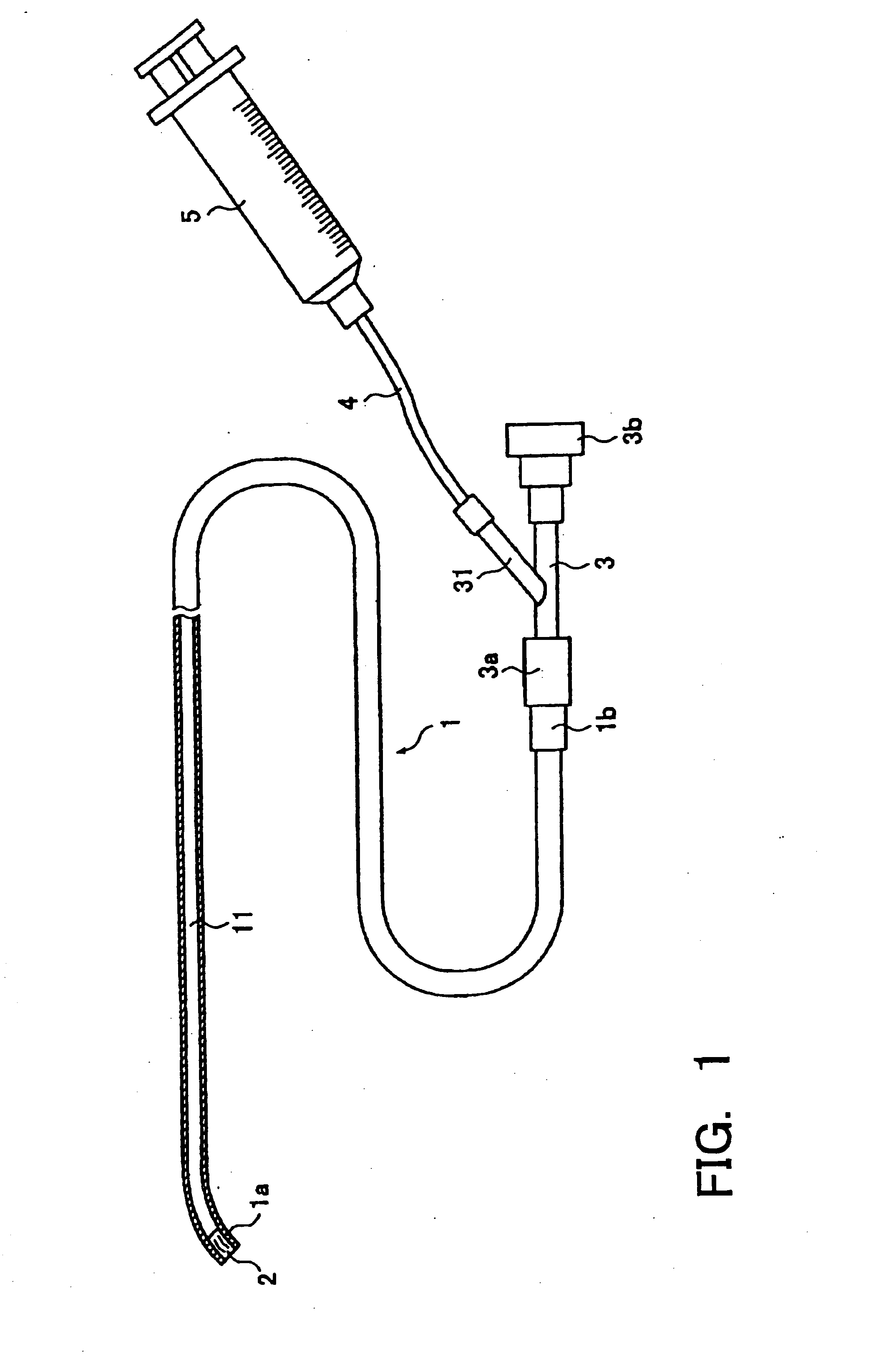
[0052] Referring to FIG. 1, an aspiration thrombectomy catheter assembly according to one illustrated and disclosed embodiment includes a flexible elongate catheter tube 1 having a lumen 11 defined therein. The lumen 11 has a circular cross-sectional shape. The thrombectomy catheter assembly also includes a catheter hub 1b mounted on the proximal end of the catheter tube 1, a Y-shaped connector 3 connected to the catheter hub 1b at the distal end 3a and a suction device (e.g., a syringe) 5 connected to a branch 31 of the Y-shaped connector 3 via a joint tube 4.

[0053] When the catheter tube 1 is inserted into a blood vessel, the end of the catheter tube 1 which is first introduced into the blood vessel is referred to as a distal end, and the other end of the catheter tube 1 as a proximal end. Elements other than the catheter tube 1 of the thrombectomy catheter assembly will also have distal and proximal ends defined according to the positional relationship between the distal and pro...


PUM


Abstract

A catheter includes a flexible elongate catheter tube having a distal end, a proximal end, and a lumen defined therein, the proximal end being connectable to a suction device for evacuating the lumen, and a thrombus cutter disposed in the catheter tube near the distal end thereof, the thrombus cutter including at least one cutting edge directed radially inward from an inner wall surface of the lumen

Description

TECHNICAL FIELD [0001] This invention generally relates to a catheter, and more particularly, to an aspiration thrombectomy catheter including a thrombus cutter. BACKGROUND OF THE INVENTION [0002] Thrombectomy catheters have been used to continuously aspirate (i.e., draw) a blood clot from a blood vessel into the catheter lumen so as to remove the blood clot from the blood vessel. Specifically, after the tube of a thrombectomy catheter has been inserted through the blood vessel to a position where the thrombus is present, a suction device is connected to the proximal end of the catheter and activated to develop a negative pressure in the lumen of the tube and thereby remove the thrombus from the blood vessel. [0003] One major problem that arises in using a thrombectomy catheter to remove a blood clot is that if the size (diameter) of the thrombus is greater than the inner diameter of the catheter lumen, the catheter lumen may be blocked by the thrombus. [0004] When the lumen is bloc...

Claims


Application Information

Patent Timeline
IPC IPC(8): A61B17/22
CPCA61B17/22A61B2217/005A61B2017/320775A61B17/3207
Inventor YAMANE, MASAHISAITOU, TAKENARIFUKUOKA, TETSUYA
Owner TERUMO KK
Why Eureka
Try Eureka