Method and apparatus for operating a gas turbine engine

a gas turbine engine and gas turbine technology, applied in the direction of machines/engines, liquid fuel engines, instruments, etc., can solve the problems of increasing vibration, facilitating an increase in maintenance costs, and foreign objects entering the engine, so as to facilitate the identification of gas turbine engine impulse events and facilitate the identification of gas turbine engine impulses

Inactive Publication Date: 2007-10-25
GENERAL ELECTRIC CO
View PDF31 Cites 56 Cited by
  • Summary
  • Abstract
  • Description
  • Claims
  • Application Information

AI Technical Summary

Benefits of technology

[0007] In one aspect, method for operating a gas turbine engine is provided. The method includes coupling at least one sensor within the gas turbine engine to transmit a signal indicative of a vibration level of a rotor assembly within the gas turbine engine, detecting the vibration level of the rotor assembly based on the signal transmitted from the at least one sensor, comparing the detected vibration level to a predetermined vibration threshold, and generating an output if the detected vibration amplitude exceeds the threshold amplitude for a predetermined duration to facilitate identifying a gas turbine engine impulse event.
[0008] In another aspect, a monitoring system for a turbine engine including a combustor is provided. The monitoring system includes at least one sensor configured to transmit a signal indicative of a vibration level of a rotor assembly within the gas turbine engine, and an engine monitoring unit (EMU) coupled to the at least one sensor for receiving the signal transmitted therefrom, the EMU configured to detect the vibration level of the rotor assembly based on the signal transmitted from the at least one sensor and generate an output if the detected vibration level exceeds a threshold level for a predetermined duration to facilitate identifying a gas turbine engine impulse event.

Problems solved by technology

During operation, foreign objects may be ingested into the engine.
More specifically, if a foreign object strikes the fan airfoil, a portion of the composite material may be liberated from the airfoil and thus enter the engine flow path resulting in further foreign object damage to the gas turbine engine the foreign object cause the fan blade to bend or lean slightly resulting in increased vibration.
However, while both above described methods are effective in determining when an object has impacted an airfoil, each method is relatively time consuming thus facilitating an increase in the maintenance costs.
For example, while manually inspecting the gas turbine engine to identify damaged fan blades is effective, the procedure generally is relatively time consuming.
As a result, damaged fan blades may not be detected until the next maintenance event.

Method used


Image

  • Method and apparatus for operating a gas turbine engine
  • Method and apparatus for operating a gas turbine engine
  • Method and apparatus for operating a gas turbine engine

Examples


Embodiment Construction

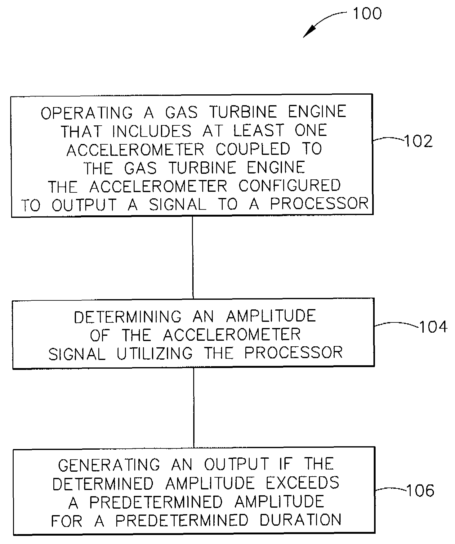
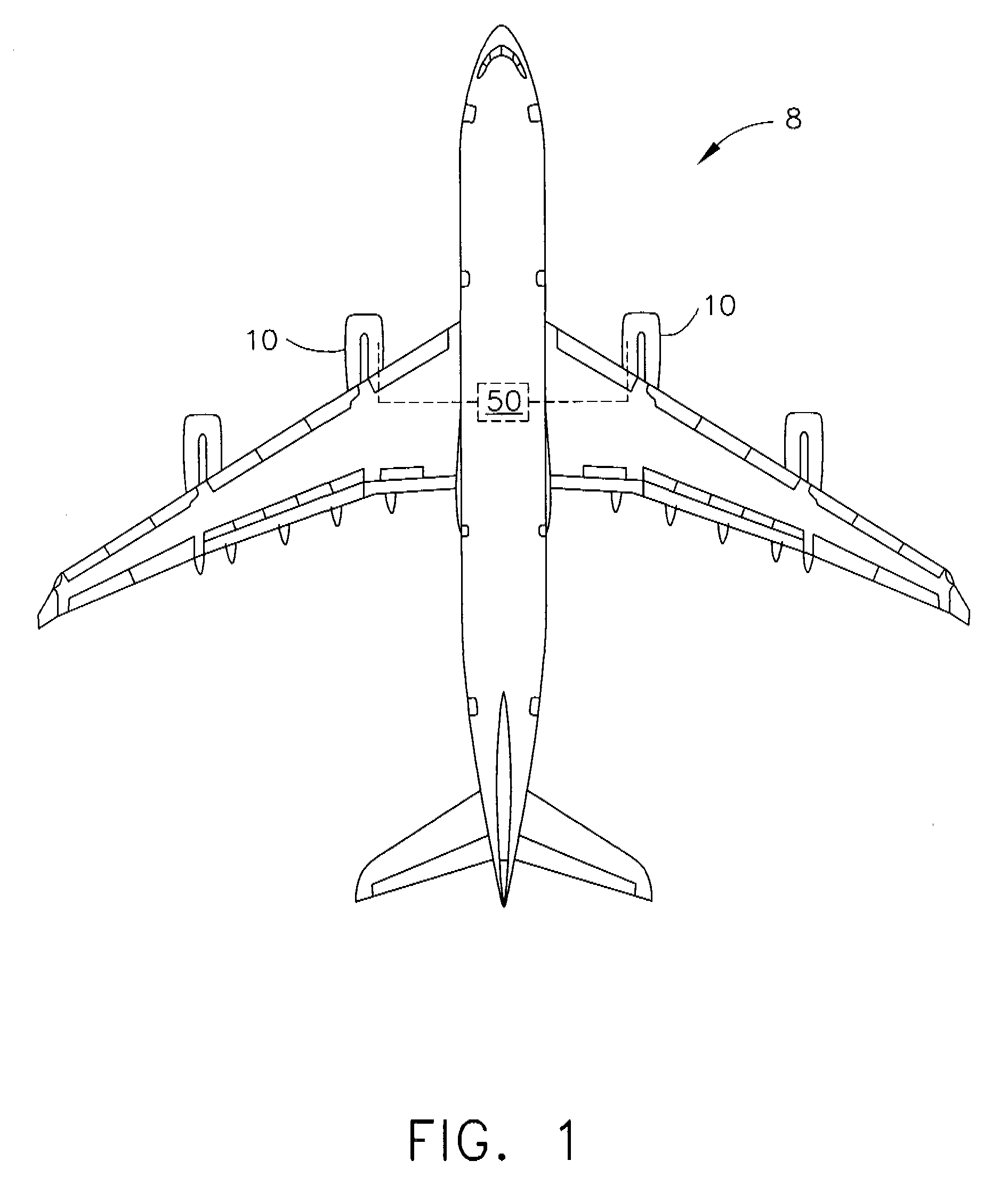
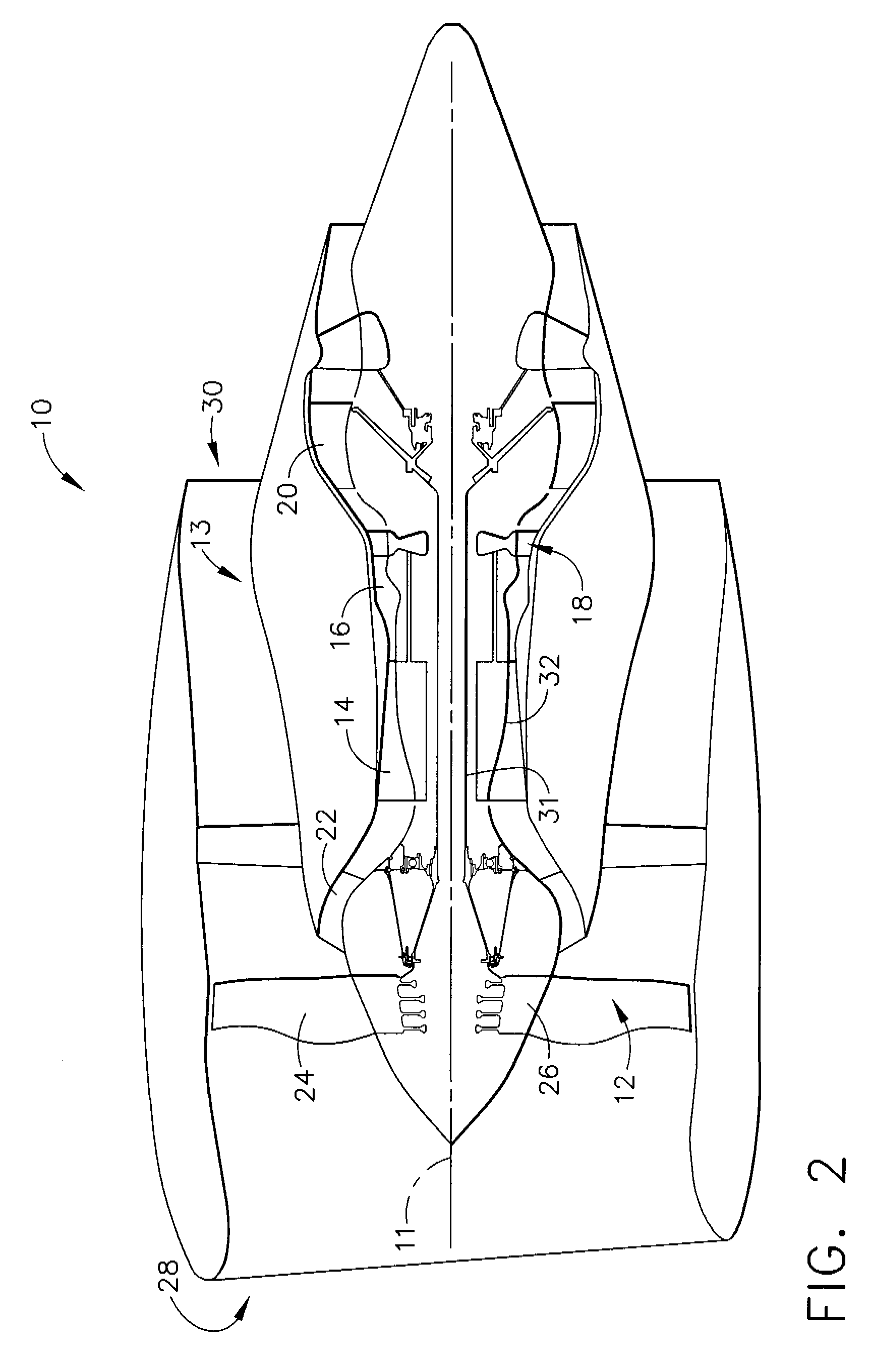
[0014]FIG. 1 is a schematic illustration of an exemplary aircraft 8 that includes at least one gas turbine engine assembly 10 and at least one engine monitoring unit (EMU) 50 that is coupled to gas turbine engine assemblies 10 and configured to receive and / or transmit information to gas turbine engine assembly 10 as will be discussed later herein. Although, FIG. 1 illustrates four gas turbine engine assemblies 10 that are coupled to a single EMU 50, it should be realized that aircraft 8 may include any quantity of gas turbine engine assemblies and may include a single EMU coupled to each respective gas turbine engine assembly. FIG. 2 is a cross-sectional view of a portion of exemplary gas turbine engine 10 (shown in FIG. 1).

[0015] In the exemplary embodiment, gas turbine engine assembly 10 has a longitudinal axis 11 and includes a fan assembly 12, and a core gas turbine engine 13 that includes a high pressure compressor 14, a combustor 16, and a high pressure turbine 18. In the exe...


PUM


Abstract

A method for operating a gas turbine engine includes coupling at least one sensor within the gas turbine engine to transmit a signal indicative of a vibration level of a rotor assembly within the gas turbine engine, detecting the vibration level of the rotor assembly based on the signal transmitted from the at least one sensor, comparing the detected vibration level to a predetermined vibration threshold, and generating an output if the detected vibration amplitude exceeds the threshold amplitude for a predetermined duration to facilitate identifying a gas turbine engine impulse event.

Description

BACKGROUND OF THE INVENTION [0001] This application relates generally to gas turbine engines and, more particularly, to a method and apparatus for identifying when gas turbine fan blade damage has occurred. [0002] Gas turbine engines typically include high and low pressure compressors, a combustor, and at least one turbine. The compressors compress air which is mixed with fuel and channeled to the combustor. The mixture is then ignited for generating hot combustion gases, and the combustion gases are channeled to the turbine which extracts energy from the combustion gases for powering the compressor, as well as producing useful work to propel an aircraft in flight or to power a load, such as an electrical generator. [0003] At least one known gas turbine fan assembly includes a plurality of rotor blades each having an airfoil that is fabricated utilizing a metallic material, such as titanium for example, and a composite material that is bonded to the surface of the airfoil. More spec...

Claims


Application Information

Patent Timeline
Patent Type & Authority Applications(United States)
IPC IPC(8): G06F19/00
CPCF01D21/003F01D21/045Y02T50/672F05D2260/96G01H1/006F04D27/001Y02T50/60F04D29/002G01H1/003F01D21/14F01D25/00F02C9/00G01M15/14
Inventor VAN DER MERWE, GERT JOHANNESBRADFORD, DAVID ALLEN
Owner GENERAL ELECTRIC CO
Why Eureka
Try Eureka