Mixed signal display for a measurement instrument

a technology of mixed signal and measurement instrument, which is applied in the direction of setting time indication, electric unknown time interval measurement, amplifier modification to reduce noise influence, etc., and can solve problems such as the inability to interpolate the sampled

Inactive Publication Date: 2007-10-25
TEKTRONIX INC
View PDF6 Cites 8 Cited by
  • Summary
  • Abstract
  • Description
  • Claims
  • Application Information

AI Technical Summary

Problems solved by technology

Since it is not possible to interpolate the sampled logic signal data, hardware was developed to sample the logic signals at rates much higher than a system clock.

Method used


Image

  • Mixed signal display for a measurement instrument
  • Mixed signal display for a measurement instrument
  • Mixed signal display for a measurement instrument

Examples


Embodiment Construction

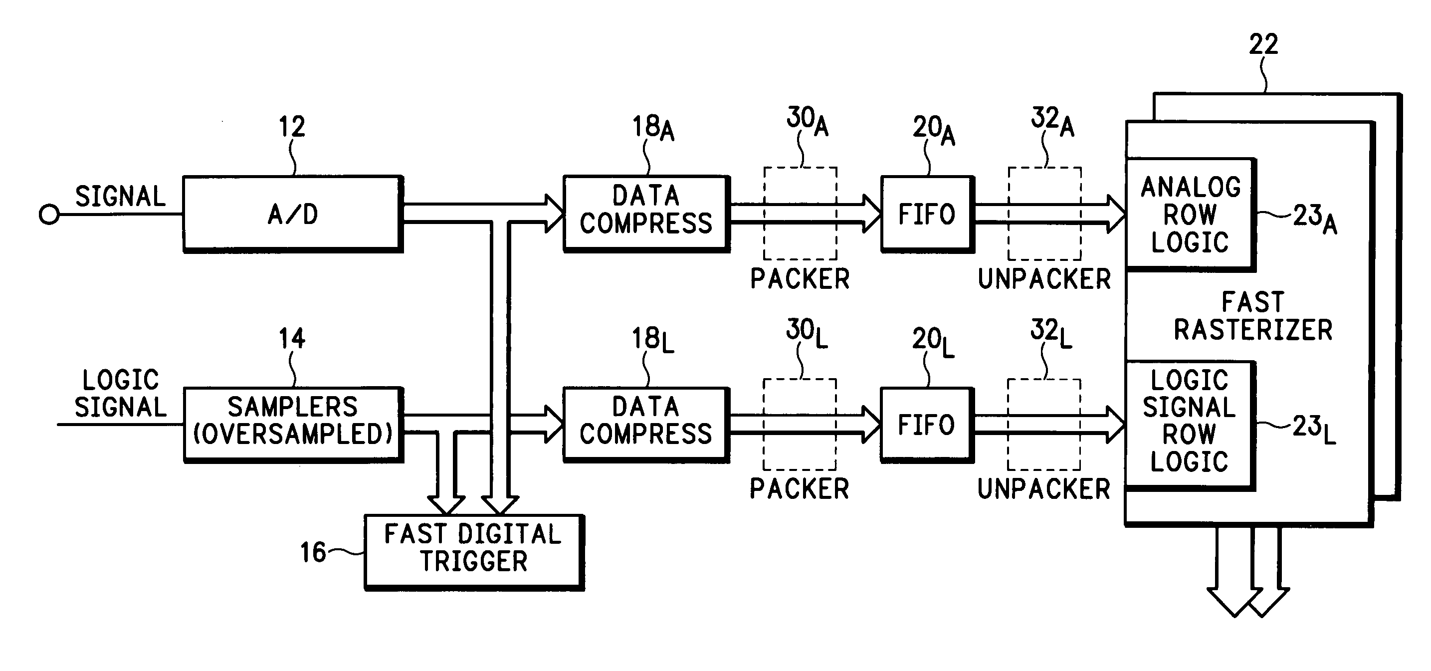
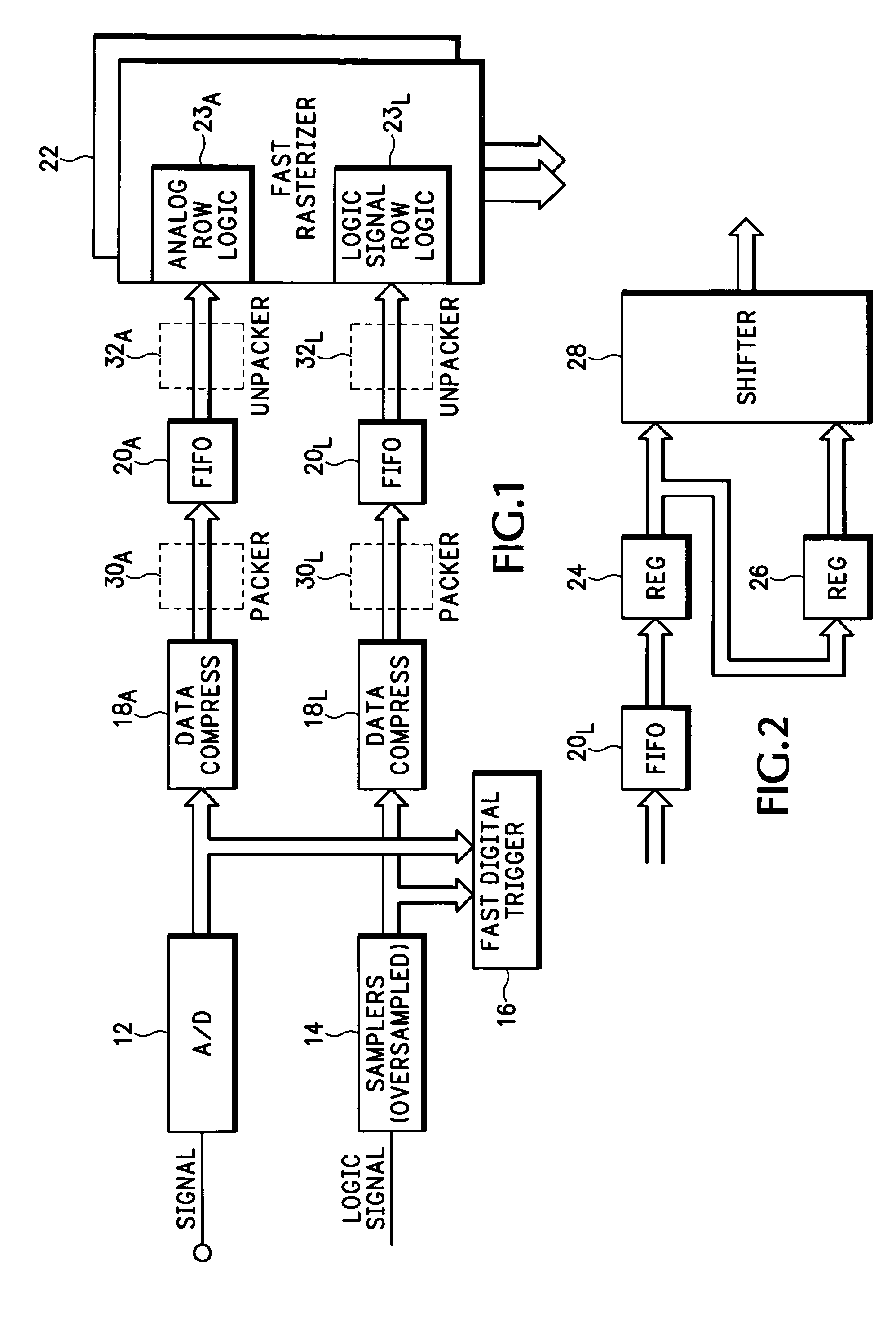
[0013] Referring now to FIG. 1 a“no dead time” data acquisition architecture for a mixed signal measurement instrument, such as a digital oscilloscope, is shown. By definition “no dead time” means all trigger events are shown on a display screen, every waveform image associated with the trigger events has a trigger event at a specified trigger location T on the display screen, and it is not necessary (or desirable) to display all trigger events at the specified trigger location.

[0014] In order to detect every trigger event, fast trigger detection is required. In addition to detecting each trigger event, the time of each trigger event relative to the acquired data is computed. Although an analog trigger generator may be realized to detect every trigger event, in the preferred embodiment analog signals being monitored are digitized by an analog-to-digital converter (ADC) 12 to produce digital analog signal data, and logic signals being monitored are oversampled by appropriate sampler...


PUM


Abstract

A mixed signal measurement instrument provides for the display of both analog and logic signal waveforms using a “no dead time” architecture. For a logic signal all trigger events are detected, the logic signal is sampled at a high rate to produce a sampled logic signal data, the sampled logic signal data are delayed to provide a pre-trigger delay and then are drawn in real time in response to the detected trigger events. A FIFO is used to delay the sampled logic signal data, with the position of the trigger event on the display being determined coarsely by an effective depth of the FIFO. The sampled logic signal data may also be compressed into compression codes prior to the FIFO. A fast drawing engine receives the sampled logic signal data from the FIFO as either data samples or compression codes, and draws a logic waveform using four rows of the drawing engine memory—one row for each of four logic states. The vertical position and height of the logic signal waveform on the display is determined when the logic waveform is transferred from the fast drawing engine to a conventional display buffer.

Description

BACKGROUND OF THE INVENTION [0001] The present invention relates to the display of acquired signal data, and more particularly to a mixed signal display for a measurement instrument that shows both analog and logic signal waveforms using a “no dead time” data acquisition architecture. [0002] In mixed signal measurement instruments analog signals are digitized and logic signals are sampled. In older instruments the digitization rate of the analog signals often matched the sample rate of the logic signals. When the digitization rate became fast enough relative to the analog signal channel bandwidth, it became possible to interpolate the digitized analog signal data so that continuous analog waveforms could be drawn on a display screen even when the display resolution is greater than the resolution of the digitized analog signal data. Since it is not possible to interpolate the sampled logic signal data, hardware was developed to sample the logic signals at rates much higher than a sys...

Claims


Application Information

Patent Timeline
Patent Type & Authority Applications(United States)
IPC IPC(8): G06F19/00G06F17/40
CPCG01R13/345G01R31/3177G01R31/3167
Inventor SULLIVAN, STEVEN
Owner TEKTRONIX INC
Why Eureka
Try Eureka