Machine Tool

Inactive Publication Date: 2007-11-01
DMG MORI SEIKI CO LTD
View PDF13 Cites 21 Cited by
  • Summary
  • Abstract
  • Description
  • Claims
  • Application Information

AI Technical Summary

Benefits of technology

[0023]Besides, the machine tool may further comprises a displacement sensing means for detecting a plumb displacement of the table body or the rotary shaft, relatively to their perpendicular position with the upper surface of the table body horizontalized, and a controlling means for controlling, based on the displacement sensed by the displacement sensing means, the load adjusting mechanism so as to adjust the load applied on the outer-peripheral locus on the rotary shaft to eliminate the displacement.
[0024]In such a configuration, although the swivel center axis, the upper surface of the table body, and the rotary shaft are horizontally equilibrated by the load applied on the rotary shaft, the table body or the rotary shaft tilts to cause its plumb position change, because the m

Problems solved by technology

In this conventional machine tool, however, the moment originating in the weight of the rotatable table itself and of the workpiece carried on the rotatable table causes the swivel center axis to downwards tilt out of the horizontal (that is, the rotating member, table body and rotary shaft are sloped), and thus prevents high precision processing of the workpiece, because with the rotational table protruding from the machine column, only one

Method used


Image

  • Machine Tool
  • Machine Tool
  • Machine Tool

Examples


Embodiment Construction

[0036]A preferred embodiment of the invention is described below with reference to the accompanying figures.

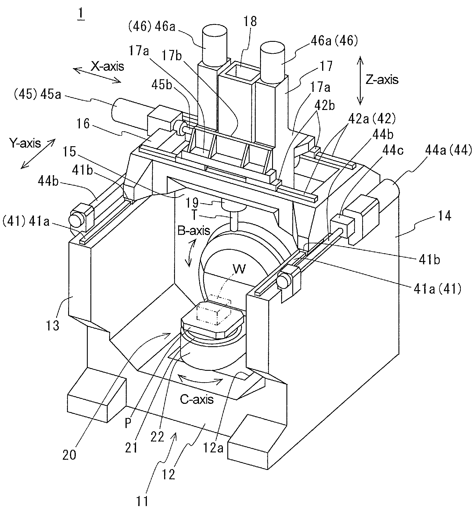
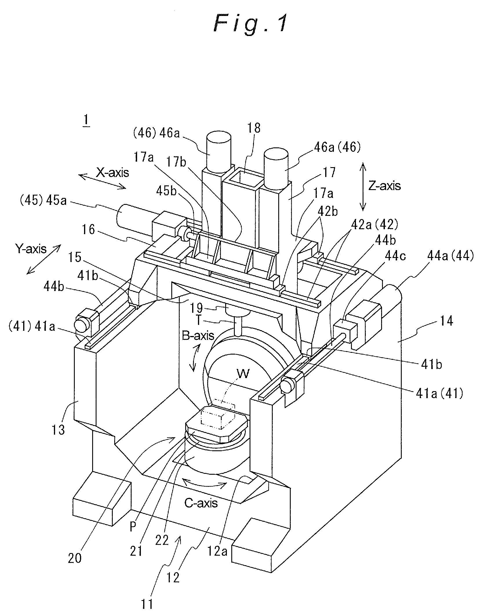
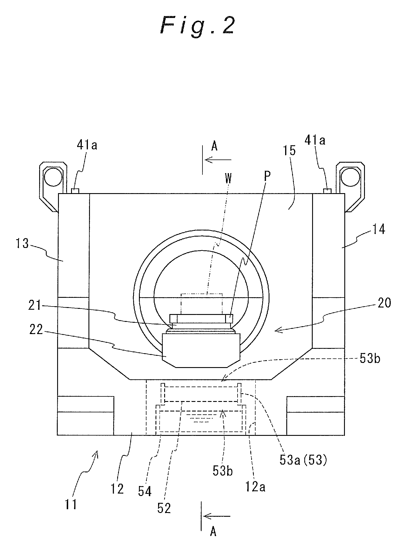
[0037]As illustrated in FIG. 1 through FIG. 6, a machine tool 1 in accordance with this embodiment of the present invention comprises: a bed (a support structure) 11; a first saddle 16 disposed on the bed 11 free to move back and forth (along the Y-axis) in a horizontal plane; a second saddle 17 disposed on the first saddle 16 free to move right and left (along the X-axis) in a horizontal plane; a spindle head 18 disposed on the second saddle 17 free to move perpendicularly (along the Z-axis); a main spindle 19, for retaining a tool T, supported by the spindle head 18 free to rotate about its axial center; a table 20, for carrying a workpiece W, arranged on the bed 11 allowing the table to swivel about a swivel center axis paralleling the Y-axis (along the “B-axis”), and configured to allow the table to rotate upon a rotational center axis paralleling the Z-axis (along the “C-...


PUM

PropertyMeasurementUnit
Timeaaaaaaaaaa
Displacementaaaaaaaaaa

Abstract

Machine tool furnished with: a table (20) free to swivel about a horizontal swivel center axis, and having a table body (22) for carrying a workpiece, and an axially rotatable rotary shaft (23) disposed with the axis of the rotary shaft (23) coinciding with the swivel center axis, with a first end of the rotary shaft affixed to the table body (22); a support structure (15) for supporting rotatably the rotary shaft (23) via a bearing (15b); a swivel drive mechanism (25) for axially rotating the rotary shaft (23); riding members (31) abutting on an outer-peripheral locus on a rotary shaft (23) second end, off a portion, supported by the bearing (15b), of the rotary shaft (23); and hold-down mechanisms (32) arranged on the support structure (15), for supporting the riding members (31) and thereby pressing on and apply a load to the rotary shaft (23) outer-peripheral locus from above.

Description

BACKGROUND OF THE INVENTION[0001]1. Technical Field[0002]The present invention relates to machine tools furnished with a table atop which a workpiece is carried, a support structure for supporting the table allowing it to swivel about a horizontal swivel center axis, and a swivel drive mechanism for swiveling the table upon the swivel center axis to index the table to a specific swivel angle position.[0003]2. Description of the Related Art[0004]Such machine tools known to date include the example disclosed in Japanese Unexamined Patent App. Pub. 10-180523. This machine tool primarily is made up of: a machine column provided upright as appropriate on the installation surface; a horizontal slide placed on the upper face of the machine column movably right and left in the horizontal plane; a vertical slide placed on the upper face of the horizontal slide movably back and forth in the horizontal plane; a main spindle disposed so that its own axis is perpendicular, for retaining a tool; ...

Claims


Application Information

Patent Timeline
IPC IPC(8): B23Q7/00B23C1/14
CPCB23C1/002B23Q1/5437B23Q11/0021B23Q11/0028Y10T29/5129Y10T409/305824Y10T29/5114Y10T409/309576Y10T29/5196Y10T29/5107Y10T409/30896Y10T408/5614Y10T408/91
Inventor OTA, HIDEHITO
Owner DMG MORI SEIKI CO LTD
Why Eureka
Try Eureka