Shock absorber for a vehicle

Inactive Publication Date: 2007-11-01
LI PO YI
View PDF8 Cites 1 Cited by
  • Summary
  • Abstract
  • Description
  • Claims
  • Application Information

AI Technical Summary

Benefits of technology

[0010] The primary objective of the present invention is to provide a shock absorber for a vehicle, wh

Problems solved by technology

After a long period of use, however, most of the existing shock absorbers are susceptible to deterioration and have the following disadvantages:
First, they merely have the function of shock absorbing but are unable to compensate and adjust the consumed damping.
Second, the components inside the shock absorber are susceptible to deterioration and fatigue, causing the problems of noise, short life, and oil lea

Method used


Image

  • Shock absorber for a vehicle
  • Shock absorber for a vehicle
  • Shock absorber for a vehicle

Examples


Example

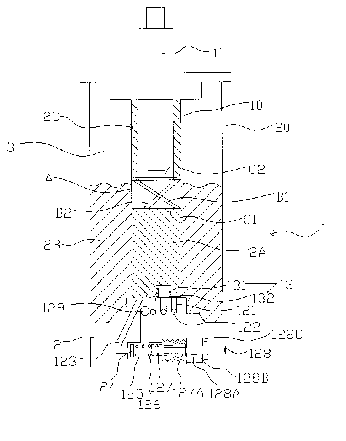
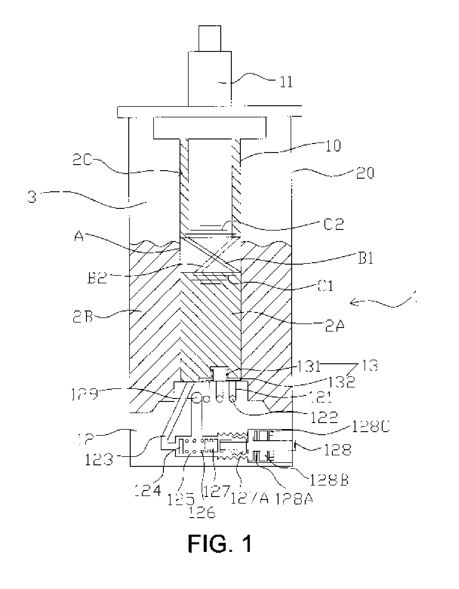
[0019] Referring to FIG. 1, a shock absorber 1 for a vehicle in accordance with the present invention comprises an inner pipe 10 and an outer pipe 20 that define a hermetic space. A piston assembly 11 is moveably received in the inner pipe 10. At an end of the piston assembly 11 are disposed a piston A, two unidirectional oil holes B1 and B2, and two valves C1 and C2. A bottom valve assembly 12 is disposed at the bottom of the inner pipe 10. The inner pipe 10 is divided by the piston A into two chambers that are filled with oil 2A and oil 2C, respectively. The outer pipe 20 is filled with nitrogen gas 3 and oil 2B. The bottom valve assembly 12 serves to separate the outer pipe 20 from the inner pipe 10.

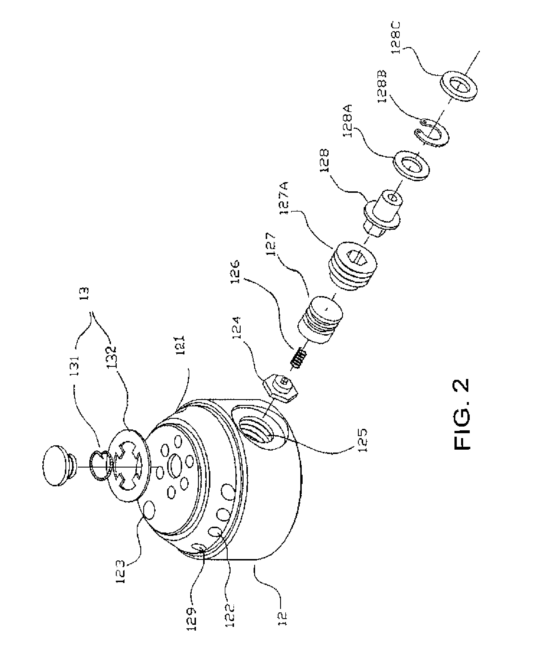
[0020] Referring to FIGS. 2-4, the present invention is characterized in that the bottom valve assembly 12 is arranged with a plurality of oil lines, including a plurality of interconnected X-axial oil lines 121, Y-axial oil lines 122, unidirectional oil lines 123, and oil guiding li...


PUM


Abstract

A shock absorber for a vehicle comprises an inner pipe, an outer pipe, and a piston assembly moveably received in the inner pipe, and a bottom valve assembly disposed at a bottom of the inner pipe. The bottom valve assembly is provided with a plurality of oil lines, including a plurality of interconnected X-axial oil lines, Y-axial oil lines, unidirectional oil lines, and oil guiding lines. A unidirectional pressure valve, a spring, a micro-adjustment bolt, a micro-adjustment screw, an oil seal, a C ring, a seal ring, and a micro-adjustment button are installed in the valve passage, respectively. By rotating the unidirectional pressure valve, the micro-adjustment screw and the micro-adjustment bolt will move and compress the spring, and a pressing force of the spring will be applied on the unidirectional pressure valve, this pressing force can also determine the flow rate of the oil.

Description

BACKGROUND OF THE INVENTION [0001] 1. Field of the Invention [0002] The present invention relates to a shock absorber, and more particularly to a shock absorber for a vehicle, which can provide a good buffering effect and is less susceptible to fatigue after a long period of use. [0003] 2. Description of the Prior Art [0004] The existing shock absorbers for a vehicle are generally divided into single tube shock absorber or double-tube shock absorber, and usually use spring and hydraulic device to achieve a shock absorbing function. After a long period of use, however, most of the existing shock absorbers are susceptible to deterioration and have the following disadvantages: [0005] First, they merely have the function of shock absorbing but are unable to compensate and adjust the consumed damping. [0006] Second, the components inside the shock absorber are susceptible to deterioration and fatigue, causing the problems of noise, short life, and oil leakage. [0007] To solve the aboveme...

Claims


Application Information

Patent Timeline
IPC IPC(8): F16F9/50
CPCF16F9/062F16F9/446F16F9/34
Inventor LI, PO-YI
Owner LI PO YI
Why Eureka
Try Eureka