Joining system head, joining system, and method of feeding and joining elements
a technology of joining system and head, which is applied in the direction of connection, welding apparatus, manufacturing tools, etc., can solve the problems of bolt damage, inability to precisely move in an arbitrary direction of space, and the robot arm alone cannot achieve such a precise linear motion. , to achieve the effect of enhancing the degree of automation
- Summary
- Abstract
- Description
- Claims
- Application Information
AI Technical Summary
Benefits of technology
Problems solved by technology
Method used
Image
Examples
first embodiment
[0091]FIG. 8 shows a transfer station 46 of the feeding means 44. At the transfer station 46, two opposed sensors 136 (for example a light barrier) are provided, detecting whether there is a bolt 36 in the transfer station 46 or not.
[0092] The feeding means 44 consists essentially of a tube or hose 138, bent off inward in the region of the transfer station 46. The bolts 36 are fed shank first from the individualizing device 52 through the feeding means 44. Consequently the head of the bolt 36 will strike the rolled edge of the tube 138 and remain so in the transfer station 46. Thus the shank of the bolt 36 protrudes from the tube 138.
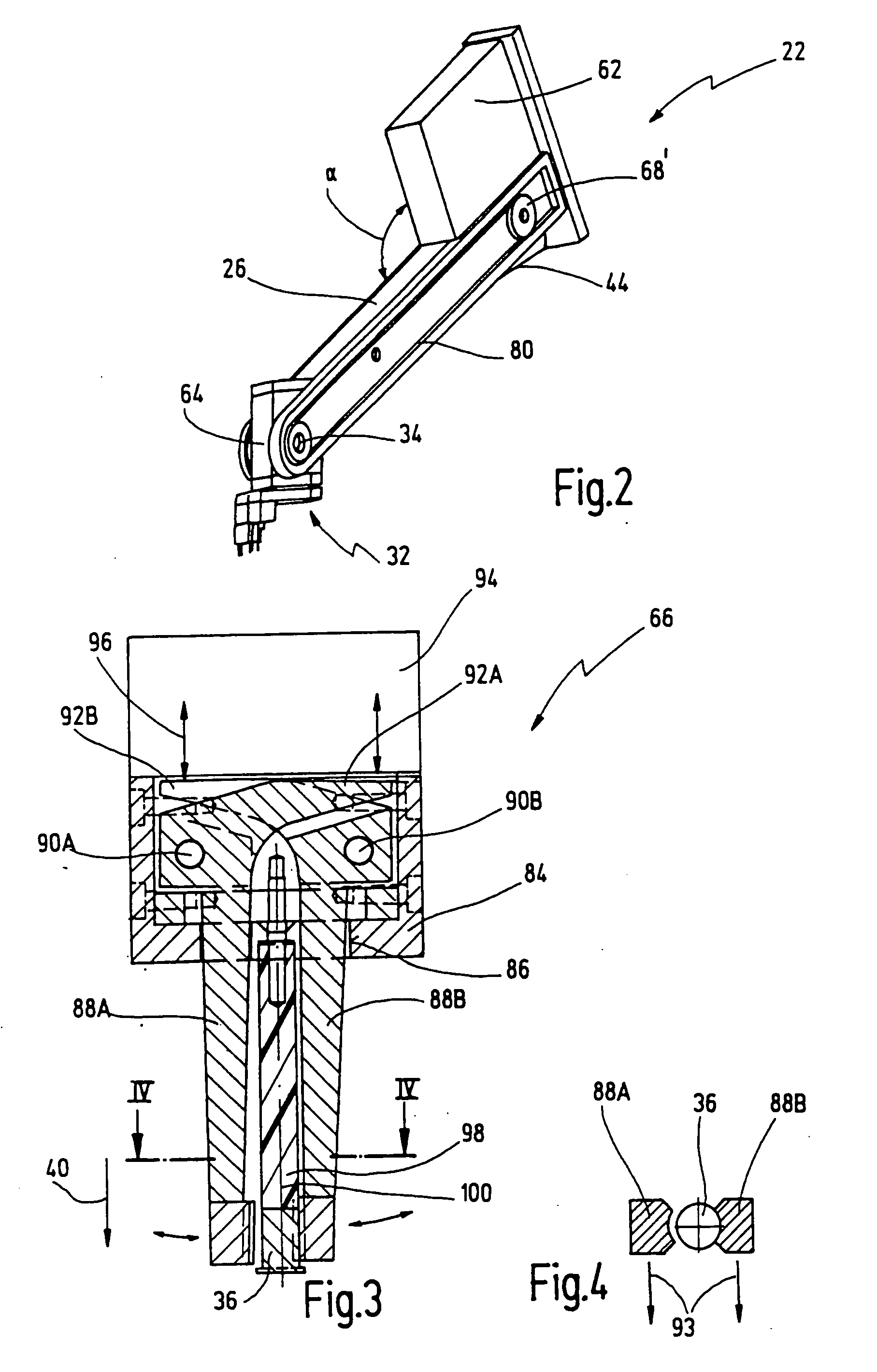
[0093] The holding means 66 can now be run with opened jaws 88A, 88B all the way to the bolt 36 and grasp it. Then the holding means 66 is swung back again, out of the plane of the paper in the representation of FIG. 8. It will be understood that at the transfer station 46, a suitable lateral recess must be provided in the tube 138, though not explicit...
third embodiment
[0096] a transfer station 46″ is shown in FIGS. 10 and 11. In this embodiment, the bolts 36 are conveyed by way of a tube 138″ into a bolt receptacle 154 of a swingable rotational segment 152. The segment 152 is rotatable about an axis 153 oriented transverse to the axis of the tube 138″ and transverse to the orientation of the bolt 36 in the transfer position.
[0097] In FIGS. 10 and 11, the segment 152 is in a transfer position. In this position, a pneumatic cylinder 156 serves to push the bolt 36 by means of a plunger 158 between two tension jaws 160, between which the bolt 36 is then hold in a defined manner. Then the segment 152 is turned back to pick up another bolt 36 in the receiving position shown dotted, flush with the tube 138″. This embodiment has the advantage that the bolts 36 can be conveyed at high speed through the tube 138″. Hence short cycle periods can be achieved.
[0098] Another embodiment of a welding head according to the invention is generally designated 170 in...
PUM
| Property | Measurement | Unit |
|---|---|---|
| angle | aaaaa | aaaaa |
| angle | aaaaa | aaaaa |
| angle | aaaaa | aaaaa |
Abstract
Description
Claims
Application Information
 - R&D
- Intellectual Property
- Life Sciences
- Materials
- Tech Scout
- Unparalleled Data Quality
- Higher Quality Content
- 60% Fewer Hallucinations
Browse by: Latest US Patents, China's latest patents, Technical Efficacy Thesaurus, Application Domain, Technology Topic, Popular Technical Reports.
© 2025 PatSnap. All rights reserved.Legal|Privacy policy|Modern Slavery Act Transparency Statement|Sitemap|About US| Contact US: help@patsnap.com


