Direct Current Power Generator Accommodating a Bicycle Hub or Motor for Auxiliary Power, a Wheel Equipped With a Direct Current Power Generator Accommodating a Bicycle Hub or a Motor for Auxiliary Power, a Bicycle Equipped With a Direct Current Power Generator Accommodating a Bicycle Hub or a Motor for Auxiliary Power and a Direct Current Power Generator Accommodating a Bicycle Hub

a technology for auxiliary power and power generators, which is applied in the direction of bicycle equipment, optical signals, propulsion by capacitors, etc., can solve the problems of increasing the load on the bicycle pedal, reducing the efficiency of friction conduction, and requiring the strengthening of magnets, so as to achieve sufficient electric power and reduce weight

Inactive Publication Date: 2007-11-01
NDC CORPORATION
View PDF6 Cites 41 Cited by
  • Summary
  • Abstract
  • Description
  • Claims
  • Application Information

AI Technical Summary

Benefits of technology

[0022] According to the present invention, it is possible to provide a direct current power generator accommodating a bicycle hub or a motor for auxiliary power, the structure of which is simple, the weight of which...

Problems solved by technology

The conventional eight-pole friction roller power generator for bicycle, which is an exterior type power generator providing friction conductive roller and bicycle tire, has low machinery efficiency of friction conduction and increases load to bicycle pedal, for which reason a power generator accommodating a bicycle hub is proposed as mentioned in the above.
Further, winding number of coil is required to be increased and a magnet is required to be strengthened, for which reason...

Method used


Image

  • Direct Current Power Generator Accommodating a Bicycle Hub or Motor for Auxiliary Power, a Wheel Equipped With a Direct Current Power Generator Accommodating a Bicycle Hub or a Motor for Auxiliary Power, a Bicycle Equipped With a Direct Current Power Generator Accommodating a Bicycle Hub or a Motor for Auxiliary Power and a Direct Current Power Generator Accommodating a Bicycle Hub
  • Direct Current Power Generator Accommodating a Bicycle Hub or Motor for Auxiliary Power, a Wheel Equipped With a Direct Current Power Generator Accommodating a Bicycle Hub or a Motor for Auxiliary Power, a Bicycle Equipped With a Direct Current Power Generator Accommodating a Bicycle Hub or a Motor for Auxiliary Power and a Direct Current Power Generator Accommodating a Bicycle Hub
  • Direct Current Power Generator Accommodating a Bicycle Hub or Motor for Auxiliary Power, a Wheel Equipped With a Direct Current Power Generator Accommodating a Bicycle Hub or a Motor for Auxiliary Power, a Bicycle Equipped With a Direct Current Power Generator Accommodating a Bicycle Hub or a Motor for Auxiliary Power and a Direct Current Power Generator Accommodating a Bicycle Hub

Examples


first embodiment

THE FIRST EMBODIMENT

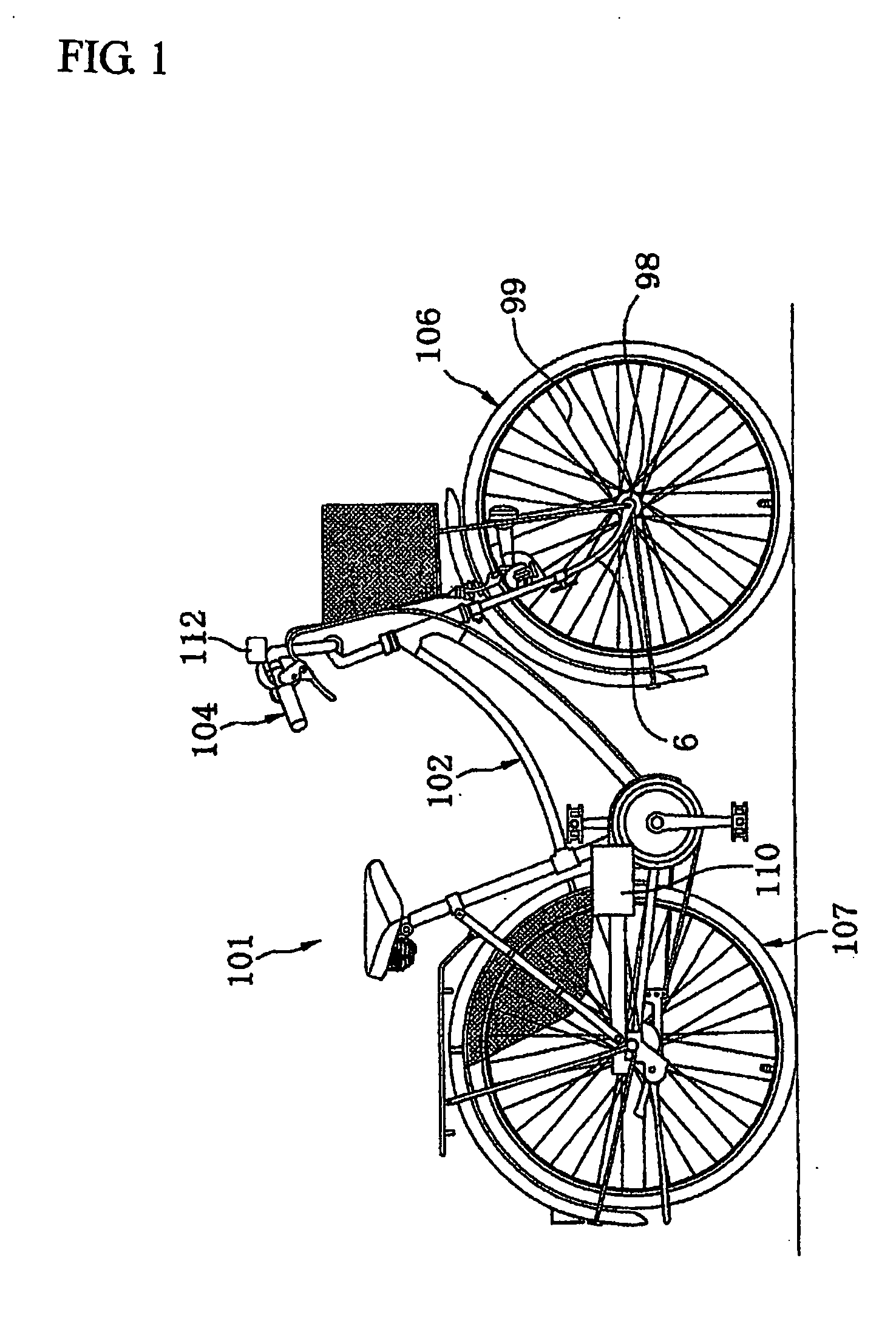
[0024] The first embodiment of the present invention is explained as follows. FIG. 1 shows a block diagram of the bicycle equipped with the power generator accommodating a bicycle hub as claimed in the present invention.

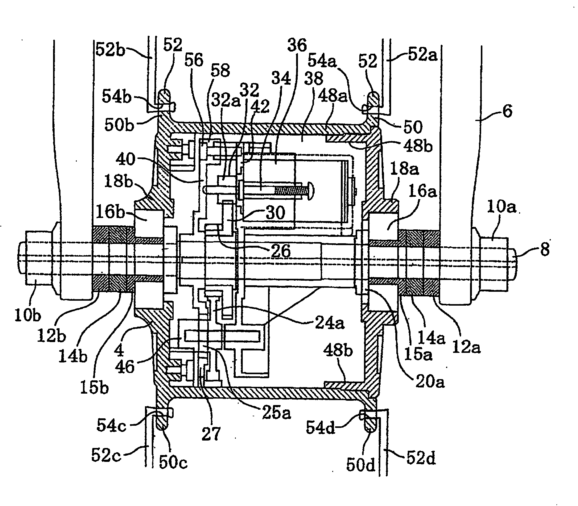
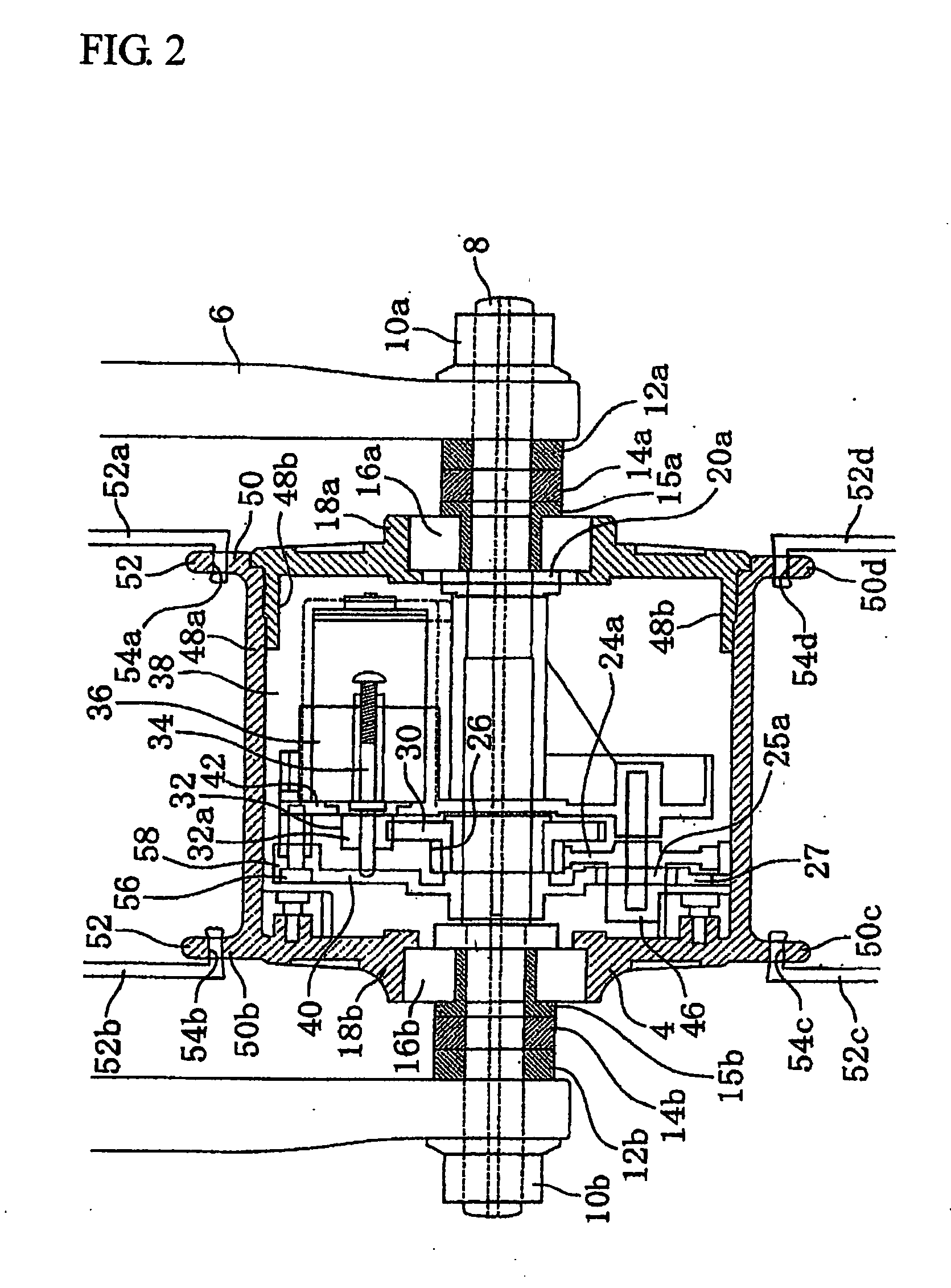
[0025] As shown in FIG. 1, Bicycle 101 equipped with a direct current power generator accommodating a bicycle hub or a motor for auxiliary power as claimed in the present invention provides Front wheel 106 and Rear wheel 107 at the front and the rear of Frame 102, and Front wheel 106 is arranged on a fork for front wheel extensionally arranged underneath Handle 104 arranged at one side of Frame 102. Front wheel 106 comprises Axis 8. rotatably penetrating through Hub 98 which is fixed through Spoke 99 to a rim. The direct current power generator accommodating a bicycle hub or the motor for auxiliary power is provided on Hub 98, whereby power may be generated for an electric lamp and for auxiliary power. Switches 66 and 70 controlling the direct cu...

second embodiment

THE SECOND EMBODIMENT

[0036] In FIG. 5, Motors 36a, 36b and 36c are motors or power generators connected in series, and Backflow prevention diode 60 and Condenser 62 are reconnected to Motor 36c. On the other hand, Headlamp switch 66 and Headlamp 64 are connected in parallel with Condenser 62. While Headlamp switch 66 is off, electromotive force generated by Motors 36a, 36b and 36c is charged in Condenser 62. On the other hand, while Headlamp switch 66 is short-circuited, Headlamp 64 is lighted and because of the existence of Condenser 62, electromotive force generated by the difference of running speed fluctuates, whereby flicker of Headlamp 64 may be prevented. Instead of Condenser 62, a rechargeable battery may also be used. In addition, as shown in FIG. 7, it is preferable that Condenser 62 (or a rechargeable battery) and Diode 60 are accommodated in a lamp or Lamp 114 to be arranged on a bicycle.

third embodiment

THE THIRD EMBODIMENT

[0037]FIG. 6 shows a circuit diagram based on the third embodiment of Direct current power generator accommodating a bicycle hub or Motor for auxiliary power as claimed in the present invention. Through Switch 66, Lamp 64 is directly lighted by means of electromotive power generated by Motors 36a, 36b and 36c. A light may also be a lamp accommodating a rechargeable battery.


PUM


Abstract

For the purpose of providing a direct current power generator accommodating a bicycle hub or a motor for auxiliary power, the structure of which is simple, the weight of which is light and which may generate sufficient electric power and also be applicable to an auxiliary to drive a bicycle without wasting excess energy, a wheel equipped with the direct current power generator accommodating a bicycle hub or the motor for auxiliary power, a bicycle equipped with the direct current power generator accommodating a bicycle hub or the motor for auxiliary power and the direct current power generator accommodating a bicycle hub, a direct current power generator accommodating a bicycle hub or a motor for auxiliary power comprising a hub connected to a bicycle wheel through a spoke, a rotational production part arranged in the hub, at least one or more motor fixed to the center of the hub and engaged with the above mentioned rotational driving part whereby charging and driving may be performed, a rechargeable battery equipped on the outside of the above mentioned hub and connected to the above mentioned motor in series, a backflow prevention diode connected to the above mentioned battery in series and a switch connected to the above mentioned backflow prevention diode in parallel are provided, and the above mentioned switch is turned on whereby the electric power charged in the above mentioned battery is supplied to the above mentioned motor for driving.

Description

[0001] A direct current power generator accommodating a bicycle hub or a motor for auxiliary power, a wheel equipped with a direct current power generator accommodating a bicycle hub or a motor for auxiliary power, a bicycle equipped with a direct current power generator accommodating a bicycle hub or a motor for auxiliary power and a direct current power generator accommodating a bicycle hub FIELD OF THE INVENTION [0002] The present invention relates to a direct current power generator accommodating a bicycle hub or a motor for auxiliary power providing a driving device which may convert rotational motion energy of a bicycle wheel to electric energy and supply the energy directly to a headlamp or charge the energy to a battery and drive the wheel by the charged battery, a wheel equipped with the direct current power generator accommodating a bicycle hub or the motor for auxiliary power, a bicycle equipped with the direct current power generator accommodating a bicycle hub or the mo...

Claims


Application Information

Patent Timeline
IPC IPC(8): B62J6/12B62J99/00B62M6/60B62M6/65
CPCB62J6/12Y02T90/14B62M6/65H02K7/116H02K7/14H02K7/1846H02K23/66B60L1/14B60L7/12B60L7/26B60L11/005B60L11/007B60L11/1805B60L11/1816B60L15/2009B60L15/2045B60L2200/12B60L2220/44Y02T10/7005Y02T10/7022Y02T10/7283Y02T10/641B62M6/60B60L50/20B60L50/40B60L50/52B60L53/14Y02T10/64Y02T10/70Y02T10/7072Y02T10/72
Inventor ISHIMOTO, ZENICHIYAMAZAKI, TOSHIHARU
Owner NDC CORPORATION
Why Eureka
Try Eureka