Thin-film piezoelectric resonator and filter circuit

Active Publication Date: 2007-11-01
KK TOSHIBA
View PDF7 Cites 66 Cited by
  • Summary
  • Abstract
  • Description
  • Claims
  • Application Information

AI Technical Summary

Benefits of technology

[0010] The invention provides a thin-film piezoelectric resonator and a filter ci

Problems solved by technology

This imposes manufacturing limitations on increasing the resonant frequency.
The SAW resonator, therefore, may not accommodate the increased frequency that is demanded to use in recent years.
Thus, it is difficult to realize, as a single device, a resonator that copes with

Method used


Image

  • Thin-film piezoelectric resonator and filter circuit
  • Thin-film piezoelectric resonator and filter circuit
  • Thin-film piezoelectric resonator and filter circuit

Examples


first embodiment

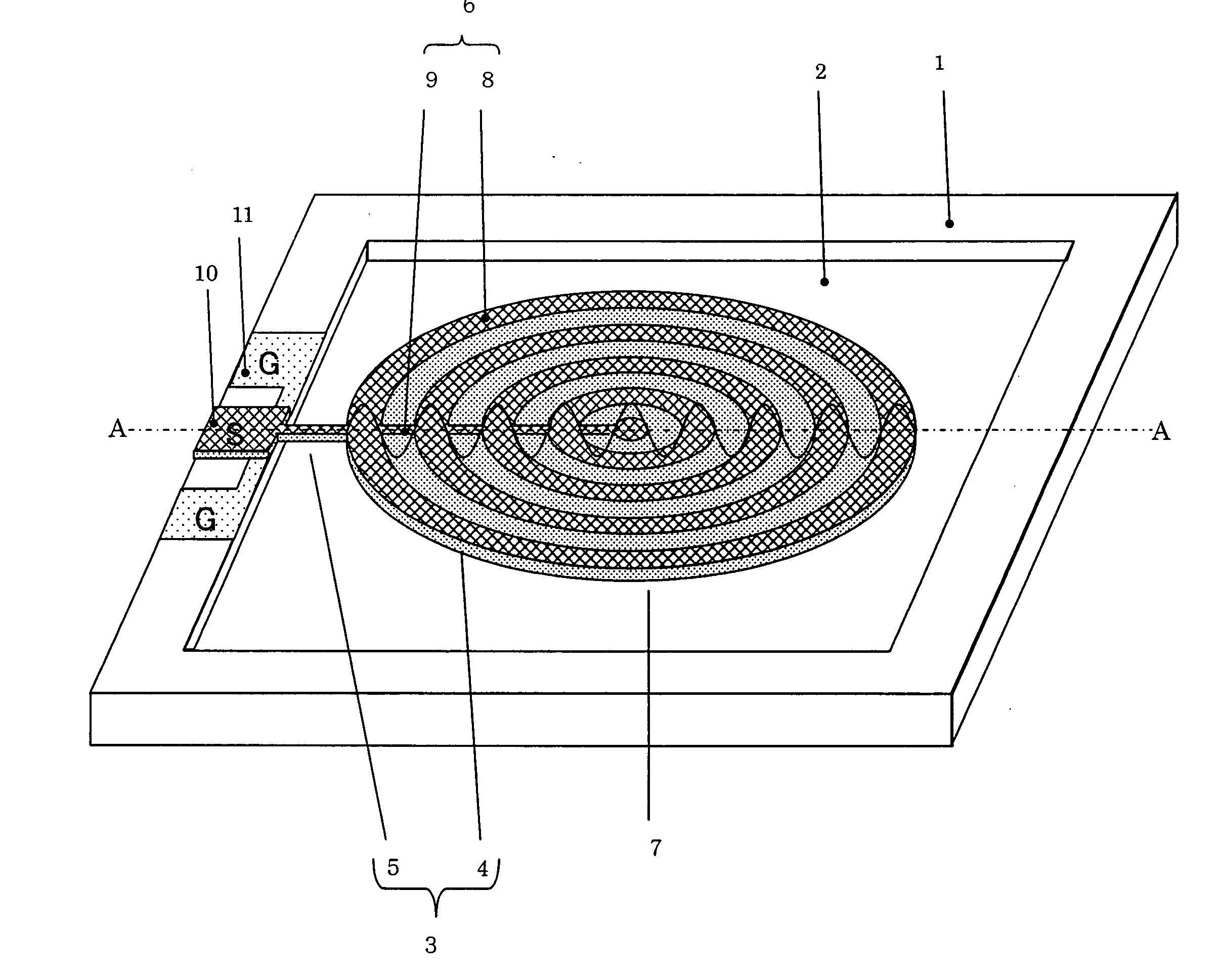
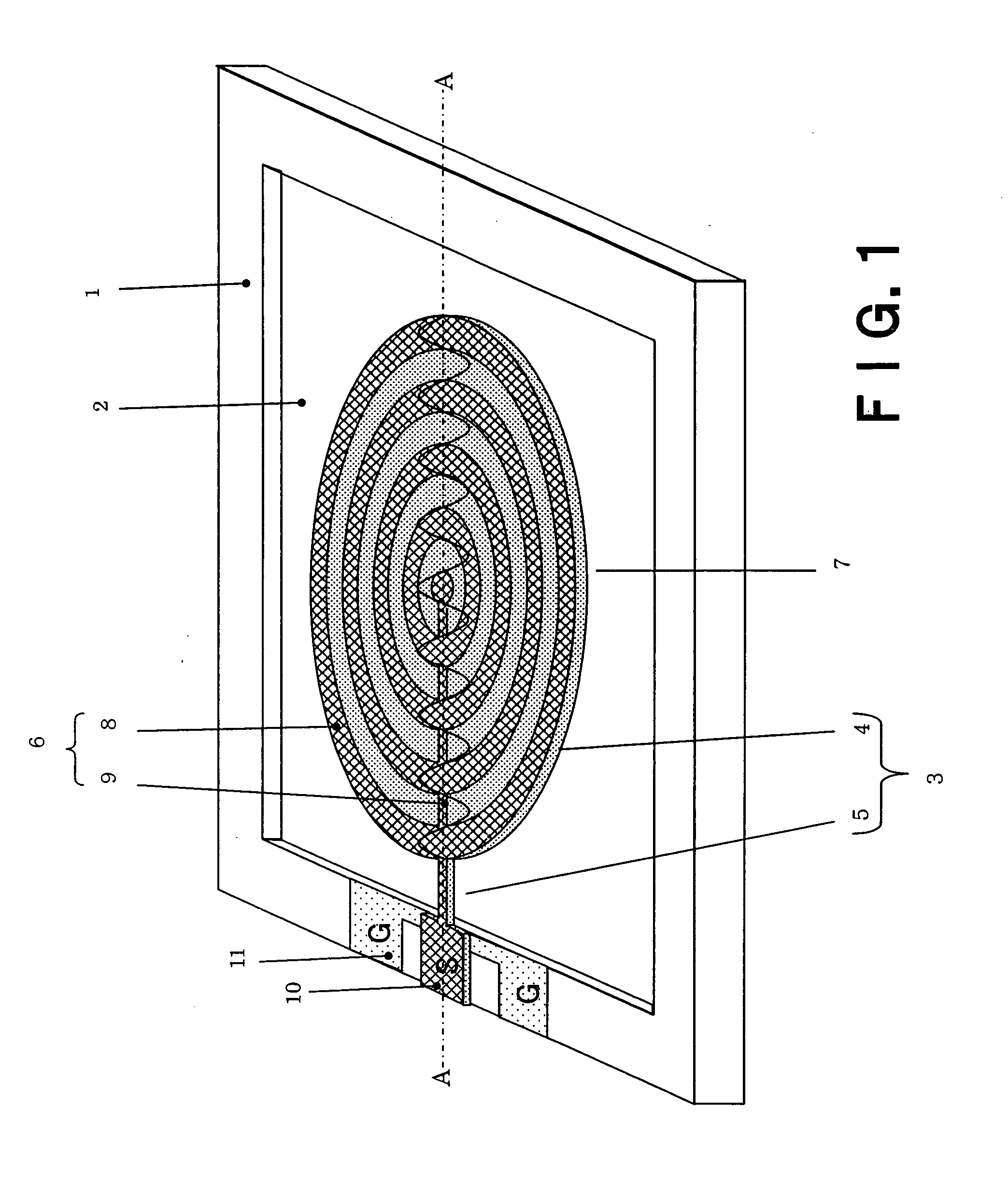
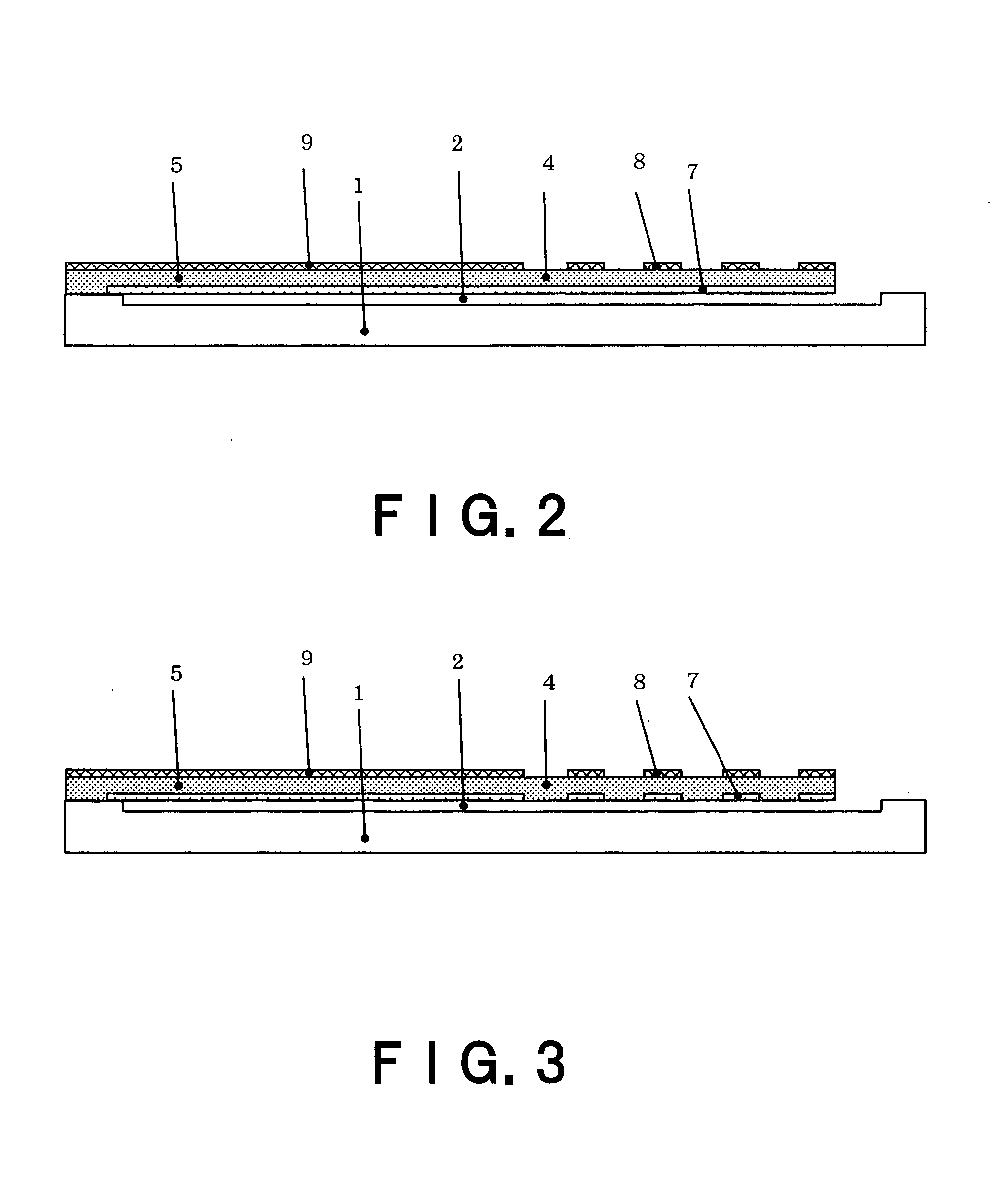
[0097]FIG. 1 is a perspective view of a one-port thin-film piezoelectric resonator according to a first embodiment of the invention. FIG. 2 is a cross-sectional view along line A-A in FIG. 1.

[0098] As shown in FIG. 1, a rectangular concave part 2 is formed in the center of a substrate 1. A piezoelectric film 3 is formed above the concave part 2. The piezoelectric film 3 has a disc part 4 and a supporting part 5 that extends from the end of the disc part 4 to the end of a substrate 1 around the concave part 2 and supports the disc part 4. The disc part 4 and the supporting part 5 are integrally formed.

[0099] An upper electrode 6 is formed above the piezoelectric film 3. A lower electrode 7 is formed under the piezoelectric film 3. The upper electrode 6 has plural annular parts 8 of a concentric shape that have the same width and are arranged at the same intervals, respectively, and a bus bar 9 (a connection part) that connects the annular parts 8 one another. The lower electrode 7 ...

application 1

of the First Embodiment

[0113] It is possible to realize various filter circuits by using the plural thin-film piezoelectric resonators in FIG. 1. For example, FIG. 4 is a plan view showing an example of a ladder-type filter constituted by using the thin-film piezoelectric resonator in FIG. 1. FIG. 5 is a circuit diagram of the filter in FIG. 4.

[0114] The ladder-type filter in FIG. 5 has a series resonator 15 including three thin-film piezoelectric resonators connected in series and a parallel resonator 16 including two thin-film piezoelectric resonators connected between connection nodes among the three thin-film piezoelectric resonators and a ground terminal.

[0115] In the ladder-type filter shown in FIGS. 4 and 5, it is necessary to match a resonant frequency of the series resonator 15 with an anti-resonant frequency of the parallel resonator 16. In this embodiment, the resonant frequency and the anti-resonant frequency were matched by setting a diameter of the piezoelectric film...

application 2

of the First Embodiment

[0116]FIG. 6 is a plan view showing an example of a lattice-type high-frequency filter constituted by using the thin-film piezoelectric resonator in FIG. 1. FIG. 7 is a circuit diagram of the filter in FIG. 6. The lattice-type filter has, as shown in FIG. 7, a first resonator 17 including thin-film piezoelectric resonators connected to first opposite sides opposed to each other, respectively, and a second resonator 18 including thin-film piezoelectric resonators connected to second opposite sides opposed to each other, respectively.

[0117] It is necessary to match a resonant frequency of the first resonator 17 with an anti-resonant frequency of the second resonator 18. In this embodiment, the resonant frequency and the anti-resonant frequency were matched by setting a diameter of the piezoelectric films 3 of the second resonator 18 larger than that of the first resonator 17 by 0.65%. When characteristics of the filter manufactured were measured, a minimum inse...


PUM


Abstract

A thin-film piezoelectric resonator has a piezoelectric film which is formed via a space on a substrate and is supported on the substrate at least one location, an upper electrode which has a plurality of electrode layers and a connection part connecting the electrode layers to each other, each of the electrode layers being formed on the piezoelectric film, having the same width and being arranged at the same interval as the width, a lower electrode formed under the piezoelectric film, a first pad which is formed on the substrate and is electrically connected to the upper electrode, and a second pad which is formed on the substrate and is electrically connected to the lower electrode.

Description

CROSS REFERENCE TO RELATED APPLICATIONS [0001] This application is based upon and claims the benefit of priority from the prior Japanese Patent Application No. 2005-379490, filed on Dec. 28, 2005, the entire contents of which are incorporated herein by reference. BACKGROUND OF THE INVENTION [0002] 1. Field of the Invention [0003] The present invention relates to a thin-film piezoelectric resonator and a filter circuit that use longitudinal resonance in a width direction of a piezoelectric film. [0004] 2. Related Art [0005] A surface acoustic wave (SAW) resonator is generally used as radio frequency (RF) and intermediate frequency (IF) filters in a mobile communication apparatus. However, since a resonant frequency of the SAW resonator is inversely proportional to a distance between comb electrodes, the distance between comb electrodes is reduced below 1 μm in a frequency domain exceeding 1 GHz. This imposes manufacturing limitations on increasing the resonant frequency. The SAW reso...

Claims


Application Information

Patent Timeline
IPC IPC(8): H01L41/047
CPCH03H9/02228H03H9/0519H03H9/582H03H9/171H03H9/132
Inventor KAWAKUBO, TAKASHINAGANO, TOSHIHIKONISHIGAKI, MICHIHIKO
Owner KK TOSHIBA
Why Eureka
Try Eureka