Electronically enabling device remotely

a technology of electromagnetic enablement and remote operation, applied in the field of locks, can solve problems such as the inability to operate devices

Inactive Publication Date: 2007-11-01
LAMAR DAVID
View PDF11 Cites 110 Cited by
  • Summary
  • Abstract
  • Description
  • Claims
  • Application Information

AI Technical Summary

Benefits of technology

[0015] If the device has a manually operable on-off switch, such as on a digital camera, the user can turn the device on and off as needed without affecting the timing circuit.
[0016] If the enabled time period concludes while the user is in the middle of an operation, the disabling of the device can be delayed. This permits a digital camera to complete the processing of an image into memory or a tool in the middle of drilling a hole to complete the task.
[0020] The tool control circuit would contain a method of authenticating the coded signal received from the electronic key thus permitting only the correct authenticated signal to activate the tool. This will reduce theft since stealing the tool without possessing the correct electronic key will make the item inoperable and valueless and readily identifiable as stolen.
[0022] The tool according to the present invention will also prevent unauthorized users from operating the tool even when it has not been stolen. This is the most likely case with children or work environments where many tools may be accessible but where restricted operation is needed.
[0024] In addition to controlling the enabling and disabling of a tool, the timing circuit could have the means to optionally control the operation of the tool based on the date and time of day rather than simply a set time duration from an activation sequence. For example, an authorized user can program a tool to activate at 8 AM and deactivate at 6 PM. This can be accomplished prior to the time of use to add flexibility.
[0025] The electronic key could be reconfigured to operate multiple electronically controlled tools in different locations. This reconfiguration would permit one operator to control a number of tools with the use of a single electronic key, rather than having to use multiple individual electronic keys.

Problems solved by technology

After the expiration of the time period, the device could not be operated without re-enabling it by means of the electronic key.

Method used


Image

  • Electronically enabling device remotely
  • Electronically enabling device remotely
  • Electronically enabling device remotely

Examples


Embodiment Construction

OF EMBODIMENTS

[0035] Although various embodiments of the invention may have been motivated by various deficiencies with the prior art, which may be discussed or alluded to in one or more places in the specification, the embodiments of the invention do not necessarily address any of these deficiencies. In other words, different embodiments of the invention may address different deficiencies that may be discussed in the specification. Some embodiments may only partially address some deficiencies or just one deficiency that may be discussed in the specification, and some embodiments may not address any of these deficiencies.

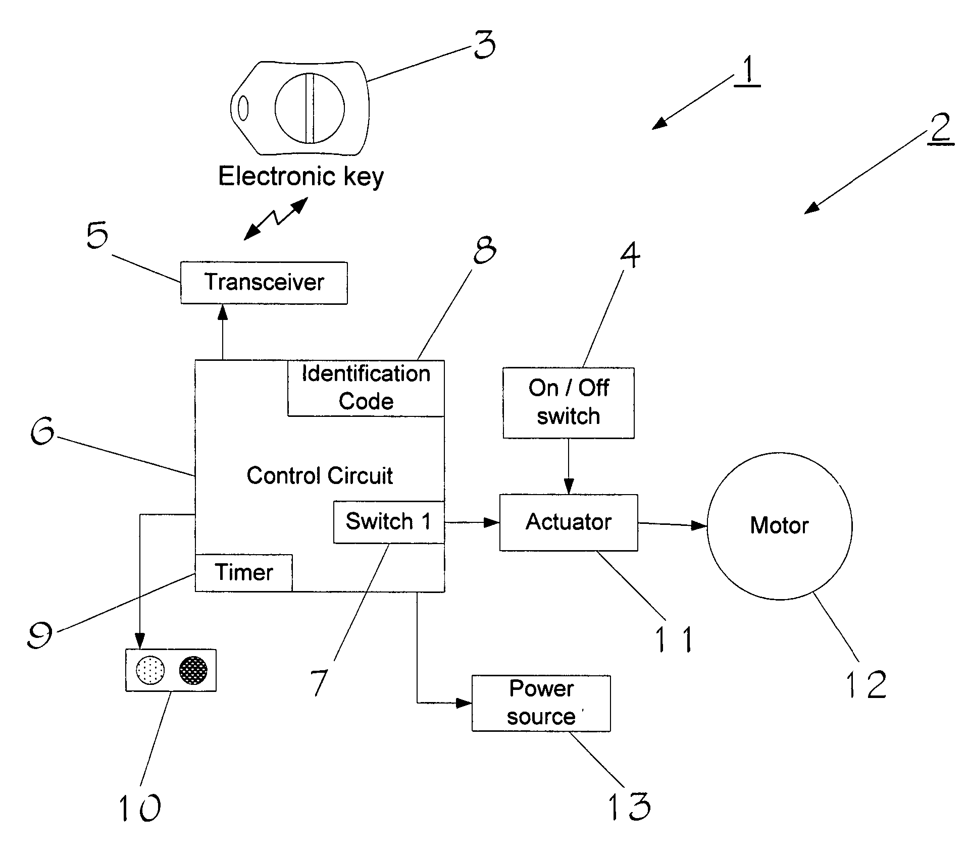
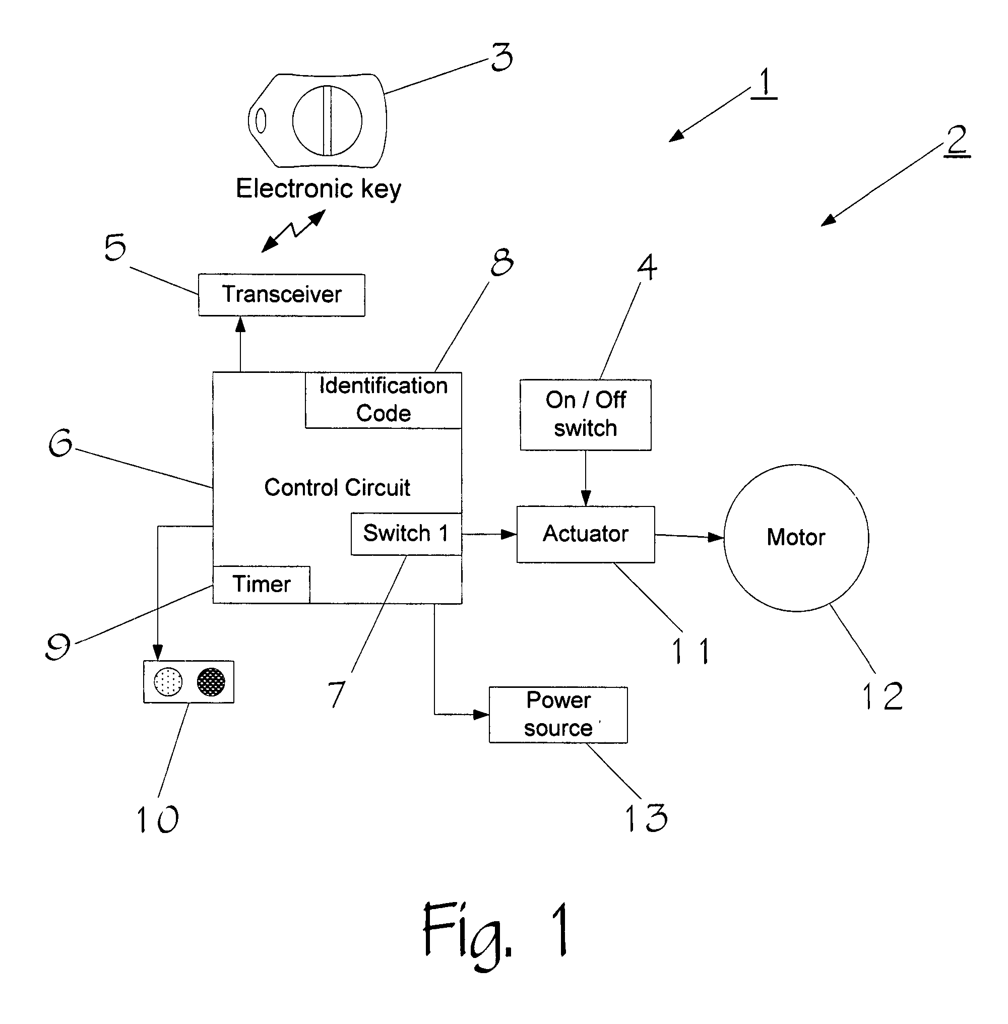
[0036] Referring to FIG. 1, a device 1 according to this invention comprises tool 2 and remote wireless electronic key 3 that can communicate with tool 2. Tool 2, for example, may be a power tool, such as a drill or saw, a lawn mower, a digital camera, computer, digital music player, video cameras, digital projectors, video game player, cell phone (wireless communi...


PUM


Abstract

A system has an electronic key that transmits a coded signal and at least one tool or other device that can receive that signal. The coded signal is compared to a coded signal stored in the tool or other device. If the coded signal authenticates the stored signal, the tool is enabled or disabled for a specified amount of time. An on / off switch then enables the user of the tool to turn the tool or other device on and off during the specified amount of time. After the specified amount of time, the tool is disabled so that the tool or other device can no longer be used. Disabling the tool may be delayed if the tool or other device is in use. The tool or other device may also contain a unique identification code that can be read by an interrogating device to identify the tool or other device.

Description

CROSS-REFERENCE TO RELATED APPLICATION [0001] This application is a continuation-in-part of U.S. patent application Ser. No. 10 / 906,807 filed Mar. 8, 2005, which in turn claims priority from U.S. Provisional Application No. 60 / 612,399, filed Sep. 24, 2004, which were both invented by David Lamar and which are both incorporated herein by reference. [0002] This application is also related to PCT / US2005 / 31809, filed Sep. 8, 2005, which is also incorporated herein by reference.FIELD [0003] The specification relates to the field of locks. BACKGROUND [0004] The subject matter discussed in the background section should not be assumed to be prior art merely as a result of its mention in the background section. Similarly, a problem mentioned in the background section or associated with the subject matter of the background section should not be assumed to have been previously recognized in the prior art. The subject matter in the background section merely represents different approaches, whic...

Claims


Application Information

Patent Timeline
Patent Type & Authority Applications(United States)
IPC IPC(8): H04B1/00
CPCB25F5/00G07C2209/08G07C9/00309
Inventor LAMAR, DAVID
Owner LAMAR DAVID
Why Eureka
Try Eureka