Raman and hyper-rman excitation using superlensing

a superlensing and superlensing technology, applied in the field oframan spectroscopy, can solve the problems of inability to focus the incident electromagnetic radiation to a “spot size", small fraction of photons are inelastically scattered by the analyte, and the use of powerful, costly laser sources is common

Active Publication Date: 2007-11-01
HEWLETT PACKARD DEV CO LP
View PDF4 Cites 9 Cited by
  • Summary
  • Abstract
  • Description
  • Claims
  • Application Information

AI Technical Summary

Benefits of technology

[0010] In one aspect, the present invention includes Raman-enhancing structures that include a substantially planar layer of dielectric material, a superlens, and at least two nanoparticles comprising a Raman-enhancing material. The layer of dielectric material has a first surface and a second, opposite surface. The superlens is configured

Problems solved by technology

However, a very small fraction of the photons are inelastically scattered by the analyte.
As a result, powerful, costly laser sources typically are used to generate high intensity incident radiation to increase the intensity of the weak Raman scattered radiation for detection.
One limitation inherent in heretofore known Raman spectroscopy systems

Method used


Image

  • Raman and hyper-rman excitation using superlensing
  • Raman and hyper-rman excitation using superlensing
  • Raman and hyper-rman excitation using superlensing

Examples


Embodiment Construction

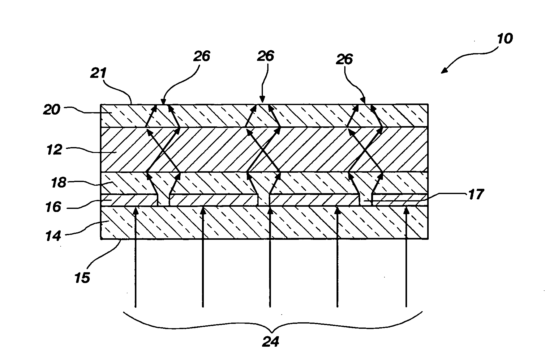
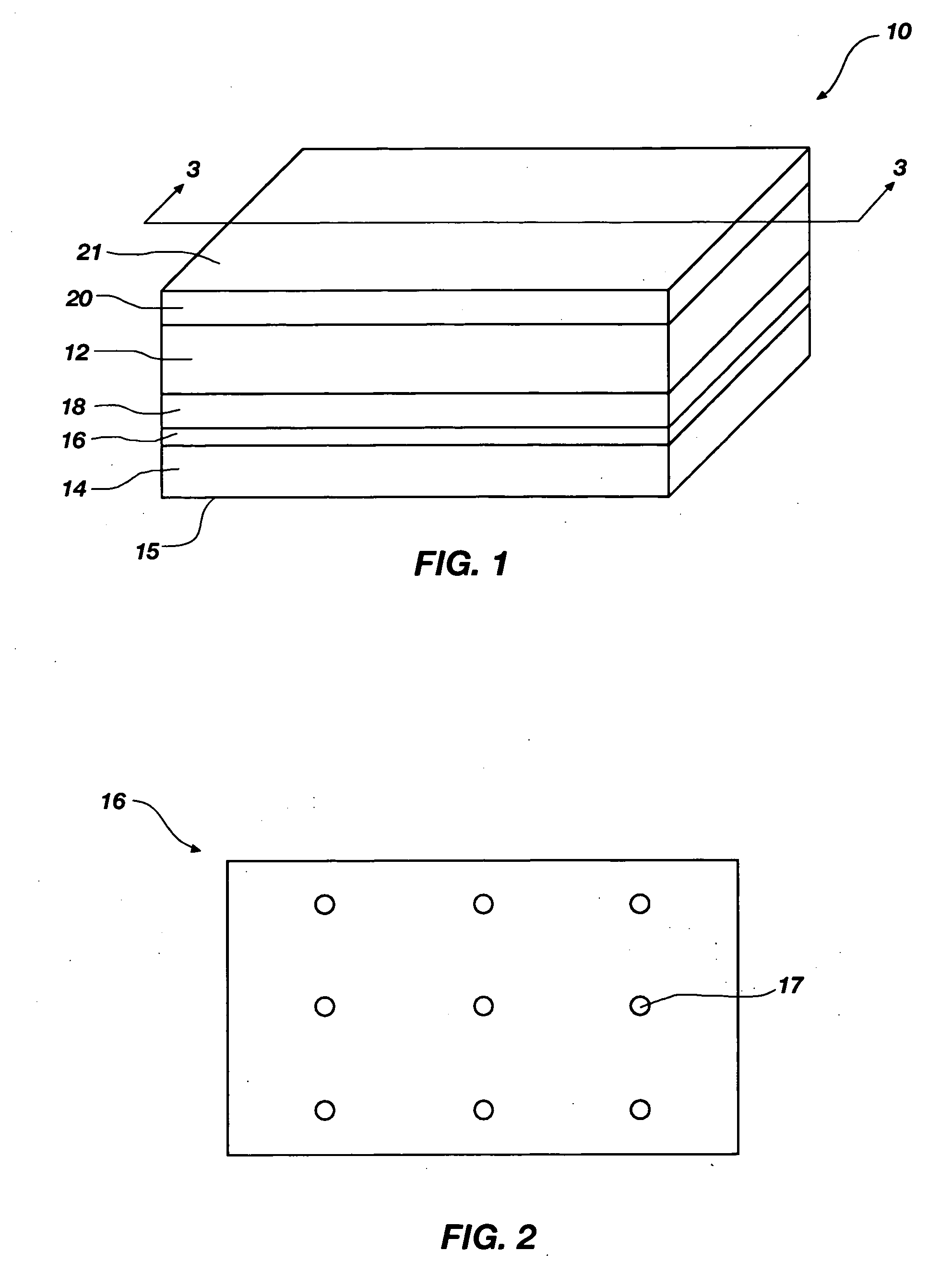
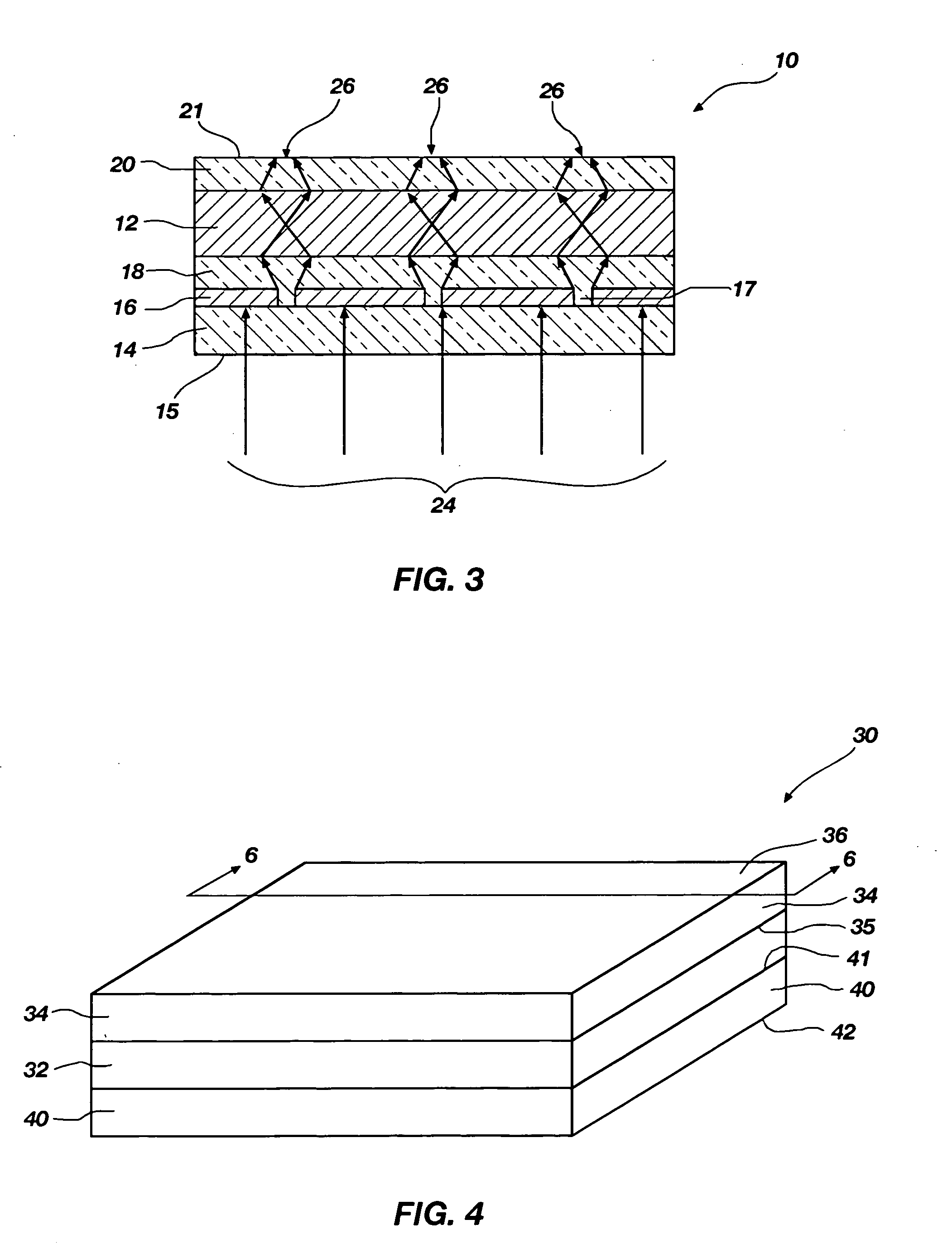
[0026] The present invention relates to Raman spectroscopy. More particularly, the invention relates to Raman-enhancing structures configured to enhance the intensity of Raman scattered radiation that is scattered by an analyte, Raman spectroscopy systems including such Raman-enhancing structures, and methods for performing Raman spectroscopy using such Raman-enhancing structures.

[0027] The term “nanostructure” as used herein means a structure that includes at least one nanoparticle. The term “nanoparticle” as used herein means a particle of any shape having cross-sectional dimensions of less than about 100 nanometers. Examples of nanoparticles include, but are not limited to, nanodots, nanowires, nanolines, nanocolumns, and nanospheres. The term “analyte” as used herein means any molecule, molecules, material, substance, or matter that is to be analyzed by Raman spectroscopy.

[0028] The term “Raman-enhancing material” as used herein means a material that, when formed into appropri...


PUM


Abstract

Raman-enhancing structures include a layer of dielectric material, a superlens configured to focus electromagnetic radiation having a wavelength greater than about 100 nanometers to a two-dimensional focal area having linear dimensions less than about 100 nanometers on a surface of the layer of dielectric material, and at least two nanoparticles comprising a Raman-enhancing material disposed proximate the focal area. Additional Raman-enhancing structures include a layer of dielectric material, a layer of conductive material, and at least two nanoparticles comprising a Raman-enhancing material disposed on a second, opposite surface of the layer of dielectric material. The layer of conductive material has a plurality of apertures therethrough that are arranged in a two-dimensional array. Methods for conducting Raman spectroscopy are performed using such structures and systems.

Description

FIELD OF THE INVENTION [0001] The present invention relates to Raman spectroscopy. More particularly, the invention relates to Raman-enhancing structures configured to enhance the intensity of Raman scattered radiation that is scattered by an analyte, Raman spectroscopy systems including such Raman-enhancing structures, and methods for performing Raman spectroscopy using such Raman-enhancing structures. BACKGROUND OF THE INVENTION [0002] Raman spectroscopy is a well-known technique for analyzing molecules or materials. In conventional Raman spectroscopy, high intensity monochromatic radiation provided by a radiation source, such as a laser, is directed onto an analyte (or sample) that is to be analyzed. In Raman spectroscopy, the wavelength of the incident radiation typically is varied over a range of wavelengths within or near the visible region of the electromagnetic spectrum. A majority of the photons of the incident radiation are elastically scattered by the analyte. In other wo...

Claims


Application Information

Patent Timeline
IPC IPC(8): G01J3/44G01N21/65
CPCG01J3/02G01N21/658G01J3/0208
Inventor WANG, SHIH-YUANLI, ZHIYONG
Owner HEWLETT PACKARD DEV CO LP
Why Eureka
Try Eureka