Magnetic reading head

Inactive Publication Date: 2007-11-01
HITACHI LTD
View PDF10 Cites 68 Cited by
  • Summary
  • Abstract
  • Description
  • Claims
  • Application Information

AI Technical Summary

Benefits of technology

[0021]According to the present invention, it is possible to obtain a magnetic reading head which facilitates adjustment of element resistance, has an extremely high magneto-resistive ratio, and has a large output that is also effective for h

Problems solved by technology

Although it is possible to raise the resistance R and to increase the value ΔR by reducing the size of the element, the feasible element area is currently limited to be about 0.025 μm2.
When the TMR element is formed to be a reading head or a magnetic field sensor, various noises are generated, and a signal-to-noise (S/N) ratio is thereby deteriorated.
When seeking to reduce the resistance i

Method used


Image

  • Magnetic reading head
  • Magnetic reading head
  • Magnetic reading head

Examples


Example

[0039]A magnetic head suitable for adopting the present invention will be described below in detail.

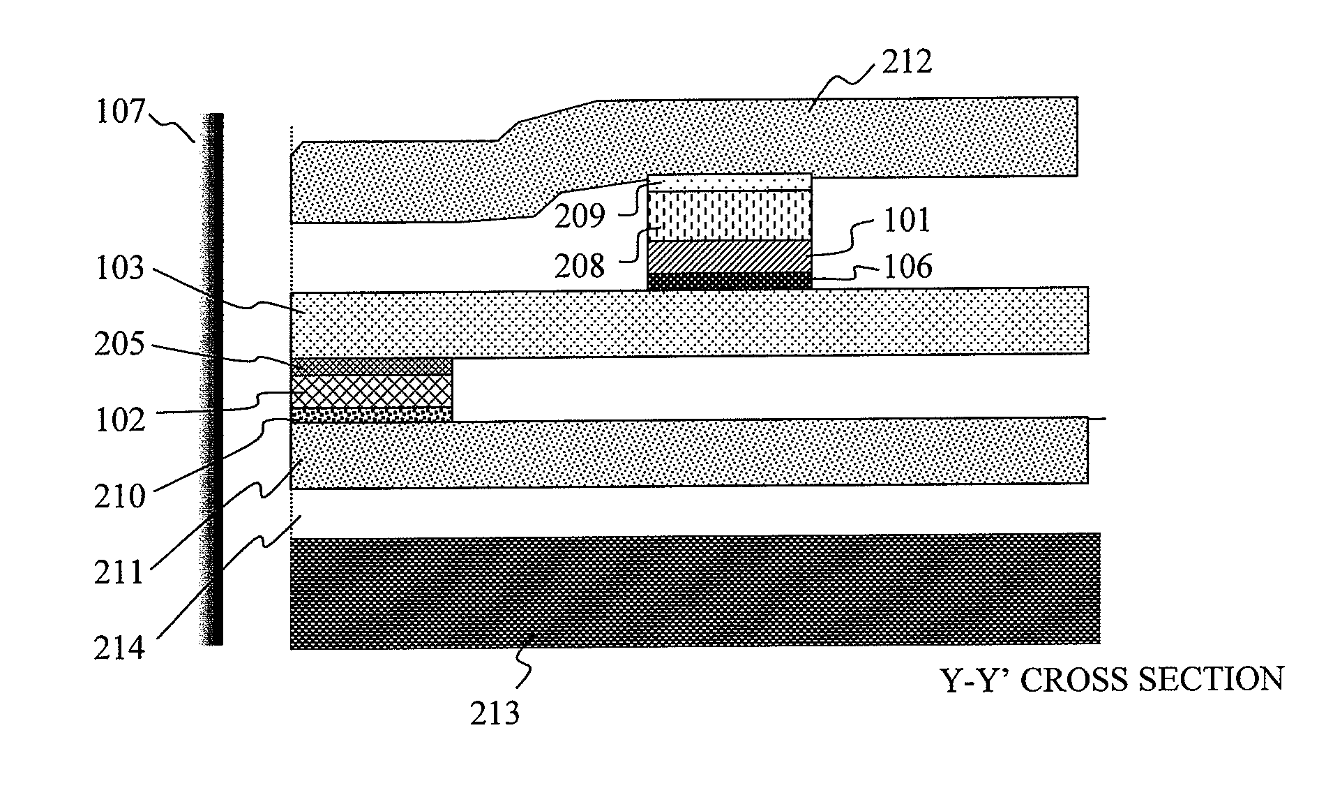
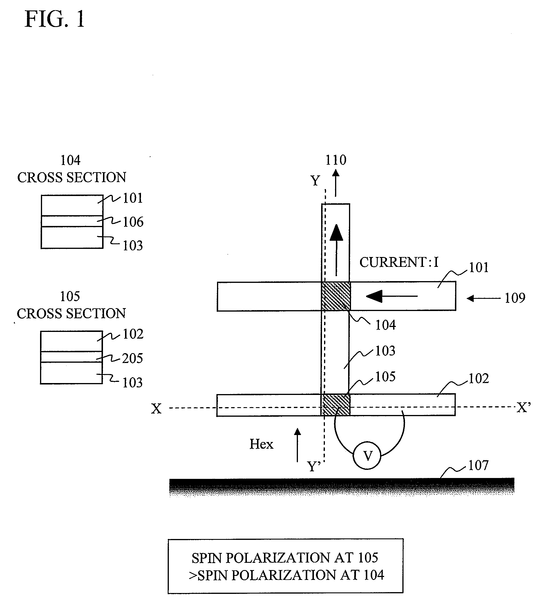
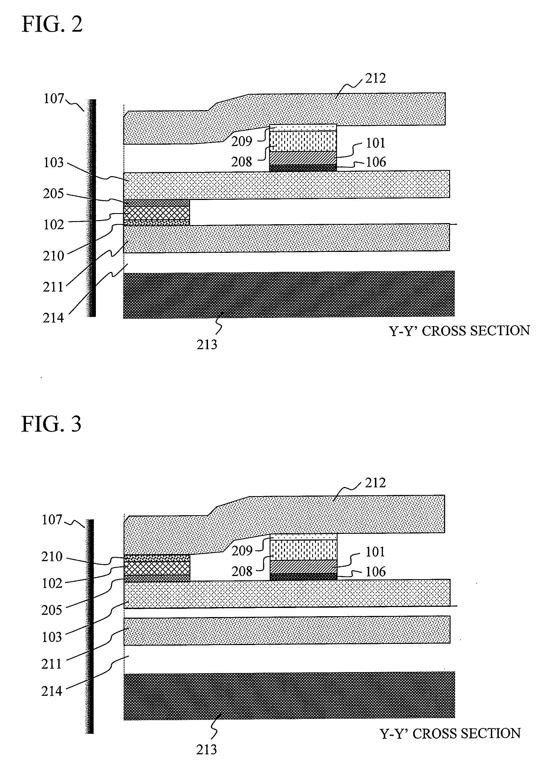
[0040]As shown in FIG. 1, the most fundamental element structure of a magnetic head, to which the present invention is applied, is provided with a linear electrode layer 103 and a first magnetic body 101 which are connected to each other with a first insulating barrier layer 106 formed on this electrode layer 103. The magnetic head is also provided with a second magnetic body 102 which is located in a different position on this electrode layer 103, and which is connected to the electrode layer 103 via an insulating barrier layer 205. A current source for supplying a current is connected to each of the first magnetic body 101 and the electrode layer 103, and the current is caused to flow in a direction indicated with an arrow 109 and then in a direction indicated with an arrow 110. Moreover, the magnetic body 102 and the electrode layer 103 are connected to a voltage-controllable circu...


PUM


Abstract

A magnetic head includes a pair of ferromagnetic electrodes, namely, a first ferromagnetic electrode layer which is in contact with a portion of a first electrode layer with a first insulating barrier layer interposed in between; and a second ferromagnetic electrode layer which is in contact with another portion of the first electrode layer with a second insulating barrier layer interposed in between. The first electrode layer and the first ferromagnetic layer collectively constitute part of a current-supplying circuit. Moreover, the first electrode layer and the second ferromagnetic layer which are in contact with the first electrode layer with the second insulating barrier layer interposed in between in a region where the two layers are not in contact with the first insulating barrier layer, collectively constitute part of a voltage-measurement circuit. Spin-polarization at the interface in an intersecting region of the second ferromagnetic layer and the second insulating barrier layer, is greater than spin-polarization at the interface in an intersecting region of the first ferromagnetic layer and the first insulating barrier layer.

Description

CLAIM OF PRIORITY[0001]The present application claims priority from Japanese application JP 2006-126363 filed on Apr. 28, 2006, the content of which is hereby incorporated by reference into this application.BACKGROUND OF THE INVENTION[0002]1. Field of the Invention[0003]The present invention relates to a magnetic reading head including a magneto-resistive effect element.[0004]2. Description of the Related Art[0005]Magnetic recording and reading apparatuses face a demand for an increase in the areal recording density in a scale over 40% every year. Magnetic recording and reading heads provided in these magnetic recording and reading apparatuses also face a demand for higher performances in terms of both of recording and reading performances. Among these heads, it is important for the magnetic reading head to satisfy the following three technical issues of: (1) improvement in higher sensitivity; (2) improvement in the narrowing of a track width; and (3) improvement in the narrowing of...

Claims


Application Information

Patent Timeline
IPC IPC(8): G11B5/33
CPCB82Y25/00G01R33/093H01F41/34G11B5/398H01F10/3204G11B5/3903G11B5/3909G11B2005/3996
Inventor TAKAHASHI, HIROMASA
Owner HITACHI LTD
Why Eureka
Try Eureka