Method for designing optical network, optical network, and computer readable medium

a technology of optical network and optical network, applied in the field of optical network design, can solve the problems of affecting the efficiency of designing, and requiring a lot of time, and achieve the effect of efficient accommodation of client signal paths

Inactive Publication Date: 2007-11-01
FUJITSU LTD
View PDF3 Cites 18 Cited by
  • Summary
  • Abstract
  • Description
  • Claims
  • Application Information

AI Technical Summary

Benefits of technology

[0022] The present invention is directed to providing a method for designing an optical network, an optical network, and a recording medium, for efficiently performing accommodation of client signal paths in an optical network by select

Problems solved by technology

The following problems may arise when paths of client signals such as SONET/SDH signals are to be accommodated in an optical network, such as the WDM network.
(1) It takes a lot of time to search for all ring topologies when the network topology is complicated.
However, the determination requires a lot of time, which inhibits efficient designing.
In a conventional method for counting all paths that can be obtained from topology information, very long time and enormous storage capacity are required as a network

Method used


Image

  • Method for designing optical network, optical network, and computer readable medium
  • Method for designing optical network, optical network, and computer readable medium
  • Method for designing optical network, optical network, and computer readable medium

Examples


first embodiment

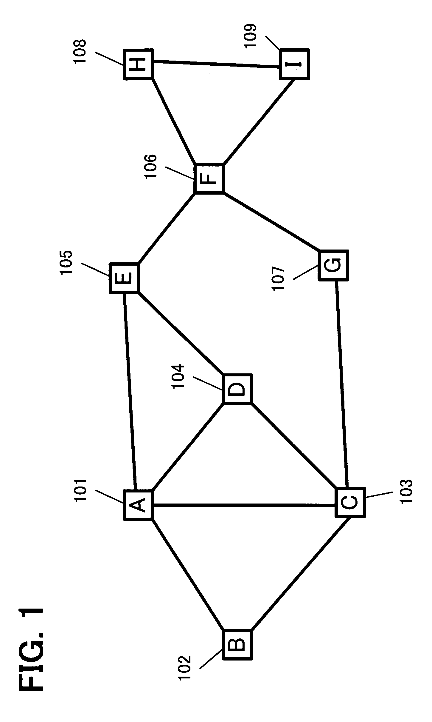
[0097] Hereinafter, the present invention is described with reference to FIGS. 4 to 13 by using the first example of the network topology shown in FIG. 1 as a representative example.

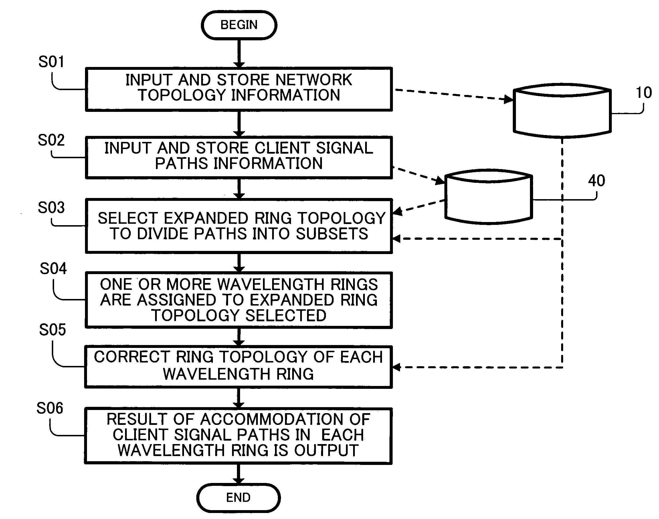
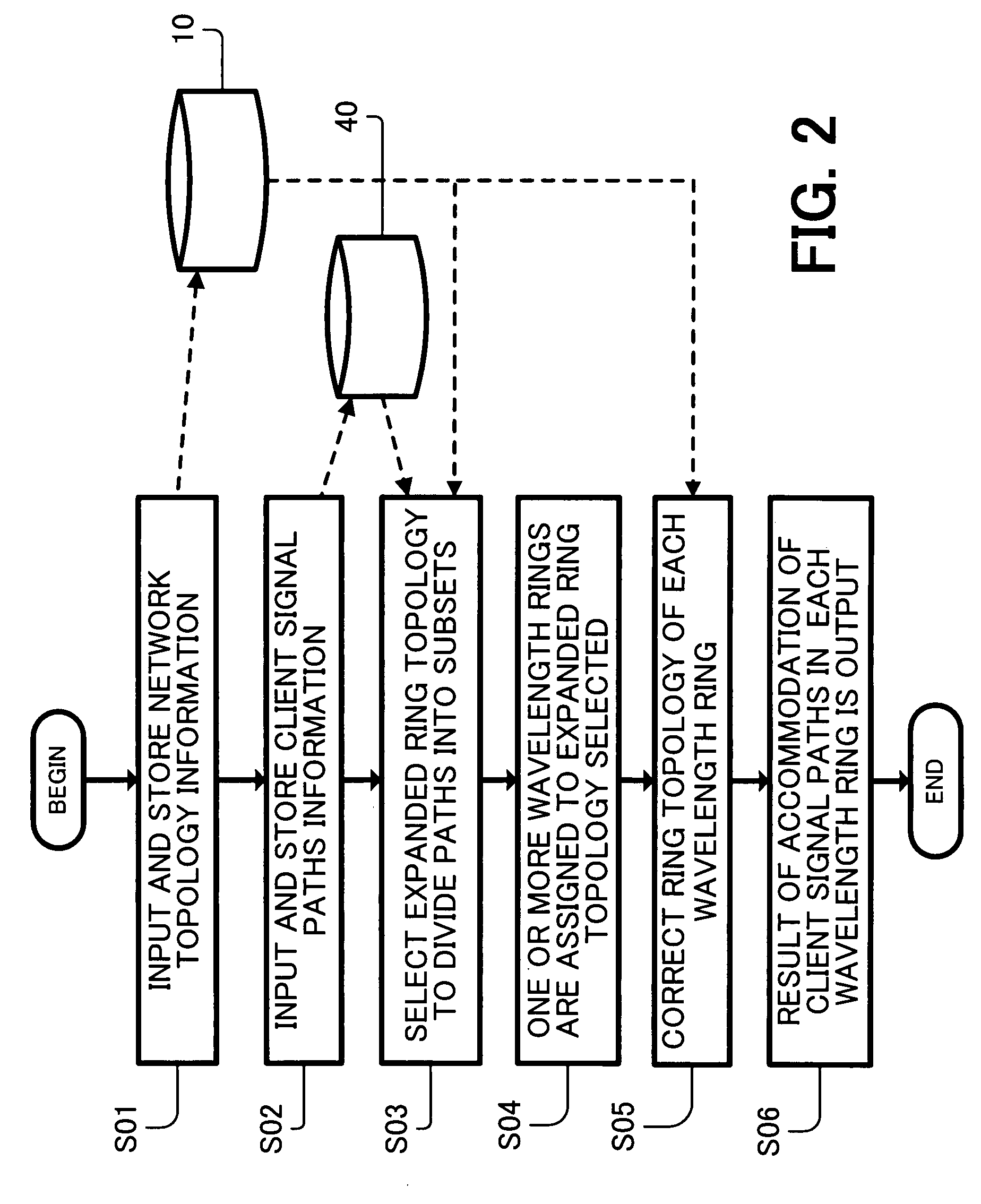
[0098]FIG. 4 shows an example of a configuration of the client signal path information according to the present invention. In this example, a set of all client signal paths to be accommodated in the designed optical network is represented as a client signal path list 40 that can be easily processed in a computer. This list 40 serves as an embodiment of the client signal path information storing part 40 shown in FIG. 2.

[0099] Each client signal path information used to design accommodation in the optical network can includes identification information of a transmitting end node and a receiving end node of traffic (hereinafter referred to as end nodes) and a traffic volume between the end nodes. Herein, the traffic volume is represented by the product of a signal bandwidth and the number of traffic paths ...

second embodiment

[0188] Hereinafter, the present invention is described with reference to FIGS. 17 to 26 by using the second example of the network topology shown in FIG. 14 as a representative example.

[0189] In the second embodiment of the present invention, a predetermined cost is assigned to each communication link between adjoining nodes so that a ring path is searched for more efficiently on the basis of the cost information.

[0190]FIG. 17 shows an example of assignment of costs to communication links according to the present invention. In this example, distance information between nodes is assigned as a cost in kilometers to respective communication links between adjoining nodes in the network topology shown in FIG. 14. Herein, the communication links between the adjoining nodes are expressed by “L(node name, node name)”. For example, the communication link between adjoining nodes A and B is expressed by “L(A, B)”. The sum of the costs between the adjoining nodes passed by the path is defined ...


PUM


Abstract

An appropriate ring topology is selected by searching network topology information on the basis of given information about client signal paths on a predetermined condition, and a wavelength ring accommodating the client signal paths and having an optimal transmission characteristic is designed on the basis of the selected ring topology. Accordingly, accommodation of client signal paths in an optical network is efficiently designed.

Description

CROSS-REFERENCE TO RELATED APPLICATION [0001] This application is a continuation-in-part of a U.S. patent application titled “METHOD FOR DESIGNING OPTICAL NETWORK, OPTICAL NETWORK, AND COMPUTER READABLE MEDIUM”, having application Ser. No. 11 / 705,582, filed on Feb. 13, 2007. This application is also related to Japanese patent application No. 2006-123908 filed Apr. 27, 2006, the entire contents of which are hereby incorporated by reference.BACKGROUND OF THE INVENTION [0002] 1. Field of the Invention [0003] The present invention relates to a technique of designing an optical network and particularly to a method for designing an optical network, an optical network, and a recording medium, adapted to efficiently accommodate paths of various client signals in an optical network of diversified network topology, such as ring, ring interconnection, and mesh. [0004] 2. Description of the Related Art [0005] In optical networks represented by a WDM (Wavelength Division Multiplexing) network, p...

Claims


Application Information

Patent Timeline
IPC IPC(8): H04B10/20
CPCH04B10/275H04J14/0227H04J14/0241H04J14/0284H04J14/0286H04J14/0283
Inventor KATAGIRI, TORUTAJIMA, KAZUYUKIHASHIGUCHI, TOMOHIRO
Owner FUJITSU LTD
Why Eureka
Try Eureka