

Method of manufacturing light-emitting diode module
Patent Information
- Authority / Receiving Office
- US · United States
- Patent Type
- Applications(United States)
- Current Assignee / Owner
- UNITY OPTO TECH CO LTD
- Publication Date
- 2007-11-01
- Estimated Expiration
- Not applicable · inactive patent
Smart Images
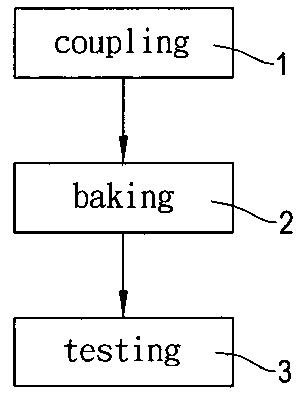
Figure 1 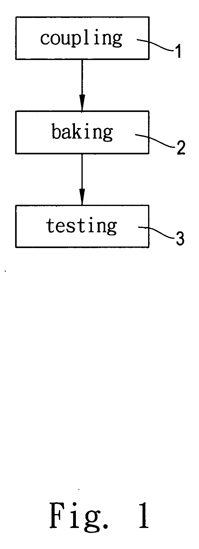
Figure 2 
Figure 3
Abstract
Description
FIELD OF THE INVENTION
[0001] The present invention relates to a method of manufacturing a light-emitting diode module with a convenient verification process and a reduced marking cost, and more particularly to a process for verifying an electronic device, for example, a light-emitting diode, mounted on a circuit board. BACKGROUND OF THE INVENTION
[0002] With the progress of technology, most persons nowadays own several electronic products on which electronic boards are unavoidably mounted. In the typical manufacturing process of a general electronic product, a circuit diagram is designed first. Next, several corresponding symbols of several electronic devices are printed on a circuit board in accordance with the circuit diagram. Next, the electronic devices can be coupled with the circuit board. Finally, a function test is performed on the circuit board to determine whether the circuit board is applicable to the electronic product.
[0003] However, in the above-mentioned process of ...