Biopsy cannula adjustable depth stop

a biopsy cannula and adjustable technology, applied in the field of biopsy devices, can solve the problems of high cost and high level of trauma to the patient, difficult to read future mammograms, and high risk of infection and bleeding in open biopsy, so as to prevent overshooting

Inactive Publication Date: 2007-11-01
DEVICOR MEDICAL PROD
View PDF25 Cites 85 Cited by
  • Summary
  • Abstract
  • Description
  • Claims
  • Application Information

AI Technical Summary

Benefits of technology

[0010] The present invention addresses these and other problems of the prior art by providing an apparatus and method for use of a depth stop device longitudinally positioned on a biopsy cannula prior to insertion into tissue. The depth stop device advantageously has an unlocked condition

Problems solved by technology

An open biopsy is a surgical procedure that is usually done as an outpatient procedure in a hospital or a surgical center, involving both high cost and a high level of trauma to the patient.
Open biopsy carries a relatively higher risk of infection and bleeding than does percutaneous biopsy, and the disfigurement that sometimes results from an open biopsy may make it difficult to read future mammograms.
Further, the aesthetic considerations of the patient make open biopsy even less appealing due

Method used


Image

  • Biopsy cannula adjustable depth stop
  • Biopsy cannula adjustable depth stop
  • Biopsy cannula adjustable depth stop

Examples


Embodiment Construction

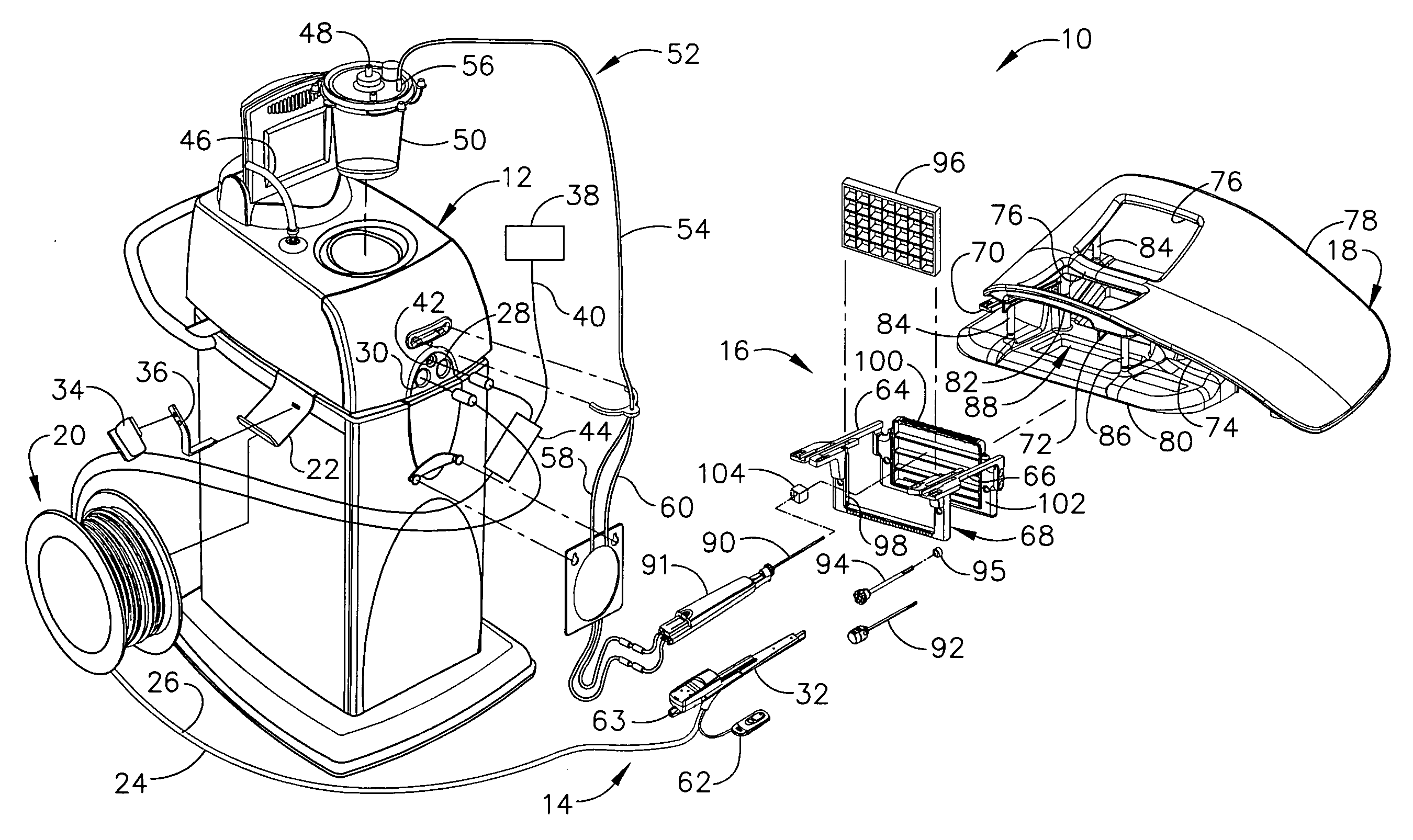
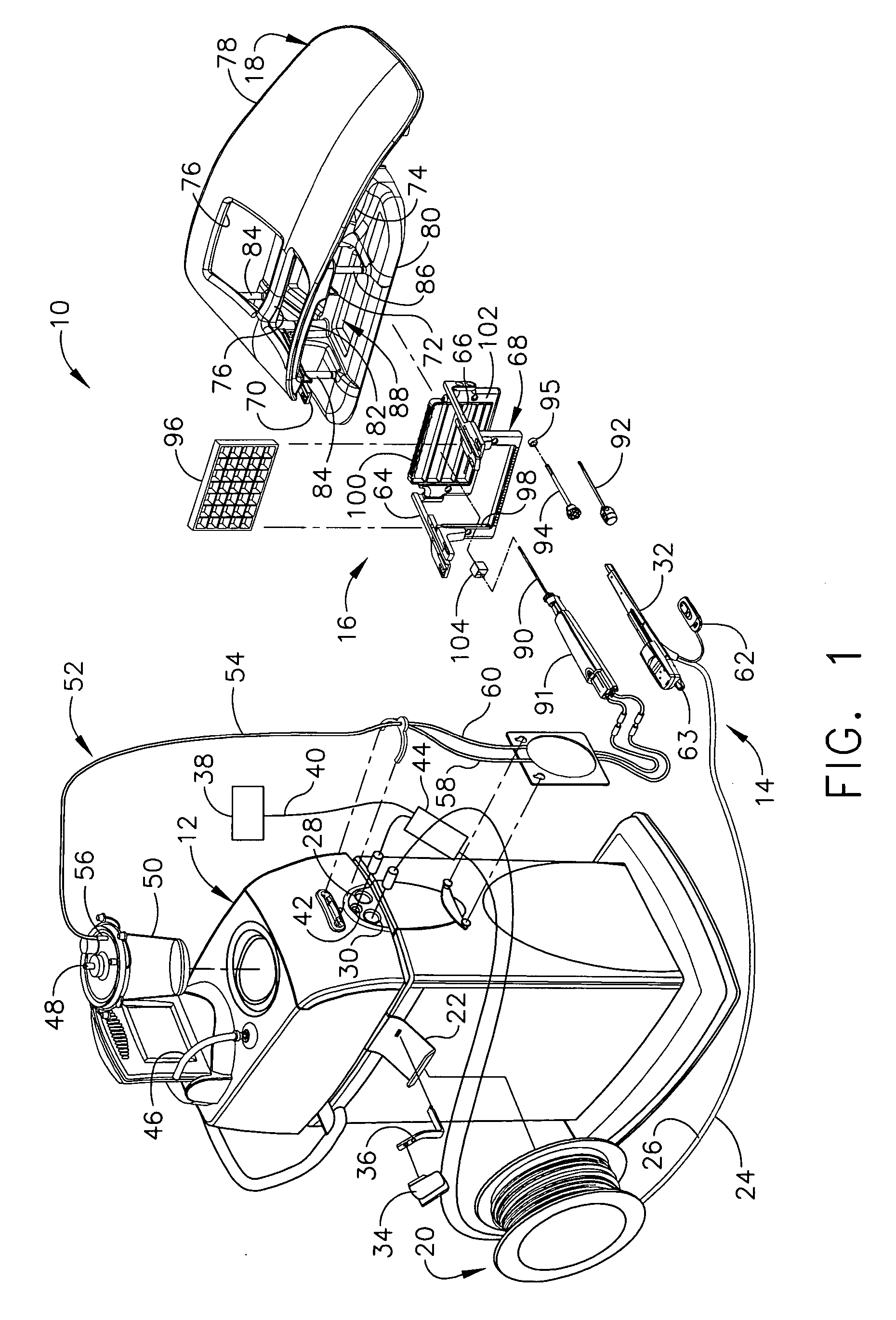
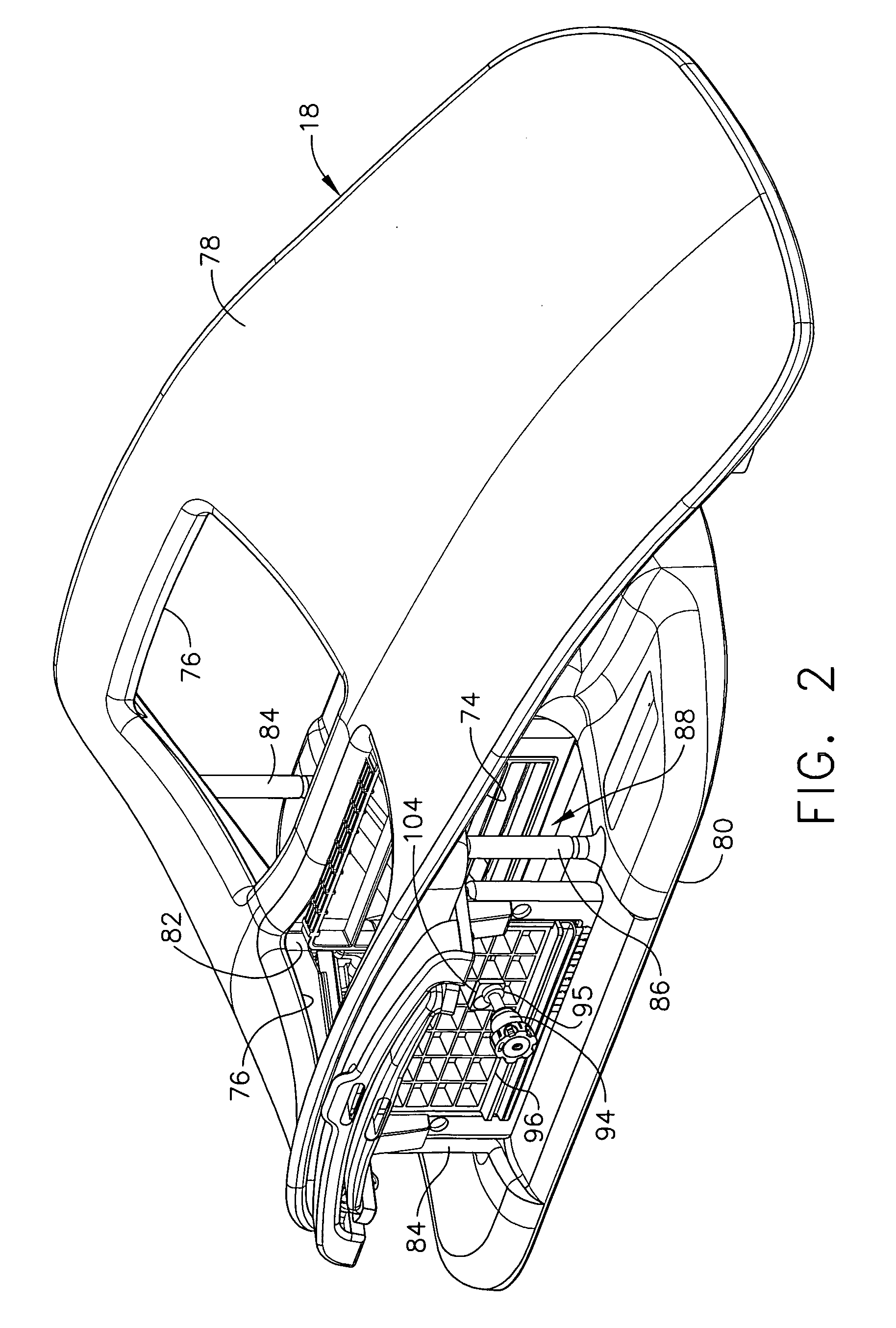
[0048] Turning to the Drawings, wherein like numerals denote like components throughout the several views, in FIGS. 1-3, a Magnetic Resonance Imaging (MRI) compatible biopsy system 10 has a control module 12 that typically is placed outside of a shielded room containing an MRI machine (not shown) or at least spaced away to mitigate detrimental interaction with its strong magnetic field and / or sensitive radio frequency (RF) signal detection antennas. As described in U.S. Pat. No. 6,752,768, which is hereby incorporated by reference in its entirety, a range of preprogrammed functionality is incorporated into the control module 12 to assist in taking these tissue samples. The control module 12 controls and powers an MRI biopsy device 14 that is positioned and guided by a localization fixture 16 attached to a breast coil 18 that is placed upon a gantry (not shown) of the MRI machine.

[0049] The control module 12 is mechanically, electrically, and pneumatically coupled to the MRI biopsy ...


PUM


Abstract

A biopsy system with a grid plate used as either a lateral or medial compression plate of a localization fixture used with a breast coil includes a rotatable guide cube that may be inserted into a desired rectangular recess in the grid plate after rotating to position a selected guide hole in the desired spatial orientation. Versions of a guide cube include those rotatable in two axes to provide additional hole positions, angled holes, enlarged circular holes that function with a rotating guide to support a noncircular biopsy instrument cannula (e.g., trocar/sleeve combination, core biopsy probe of a biopsy device) for rotation. A rotating guide may have an unlocked state for easily sliding to a selected longitudinal position thereon. Thereafter, the rotating guide is locked to serve as a positive depth stop (e.g., quarter turn locking elastomeric rings, triangular and scissor clips, and shutter depth stops).

Description

CROSS REFERENCE TO RELATED APPLICATIONS [0001] The present application is related to the co-pending and commonly-owned U.S. patent application Ser. No. ______, “GRID AND ROTATABLE CUBE GUIDE LOCALIZATION FIXTURE FOR BIOPSY DEVICE” to Hibner et al., filed on even date herewith, the disclosure of which is hereby incorporated by reference in its entirety. FIELD OF THE INVENTION [0002] The present invention relates in general to biopsy devices, and more particularly to biopsy devices having a cutter for severing tissue, and even more particularly to a localization and guidance fixture that guides insertion of a probe, or a sleeve that subsequently receives the probe of a biopsy device. BACKGROUND OF THE INVENTION [0003] When a suspicious tissue mass is discovered in a patient's breast through examination, ultrasound, MRI, X-ray imaging or the like, it is often necessary to perform a biopsy procedure to remove one or more samples of that tissue in order to determine whether the mass cont...

Claims


Application Information

Patent Timeline
IPC IPC(8): A61B10/00
CPCA61B10/0266A61B17/3403A61B2017/00796A61B2019/304A61B2017/3492A61B2019/303A61B2019/462A61B2017/3411A61B2090/033A61B2090/034A61B2090/062A61B10/0041A61B10/0275A61B10/0283A61B5/708A61B2090/036
Inventor HIBNER, JOHN A.AVIMUKA, KREENA
Owner DEVICOR MEDICAL PROD
Why Eureka
Try Eureka