
Automated event monitoring system for online reservoir simulation

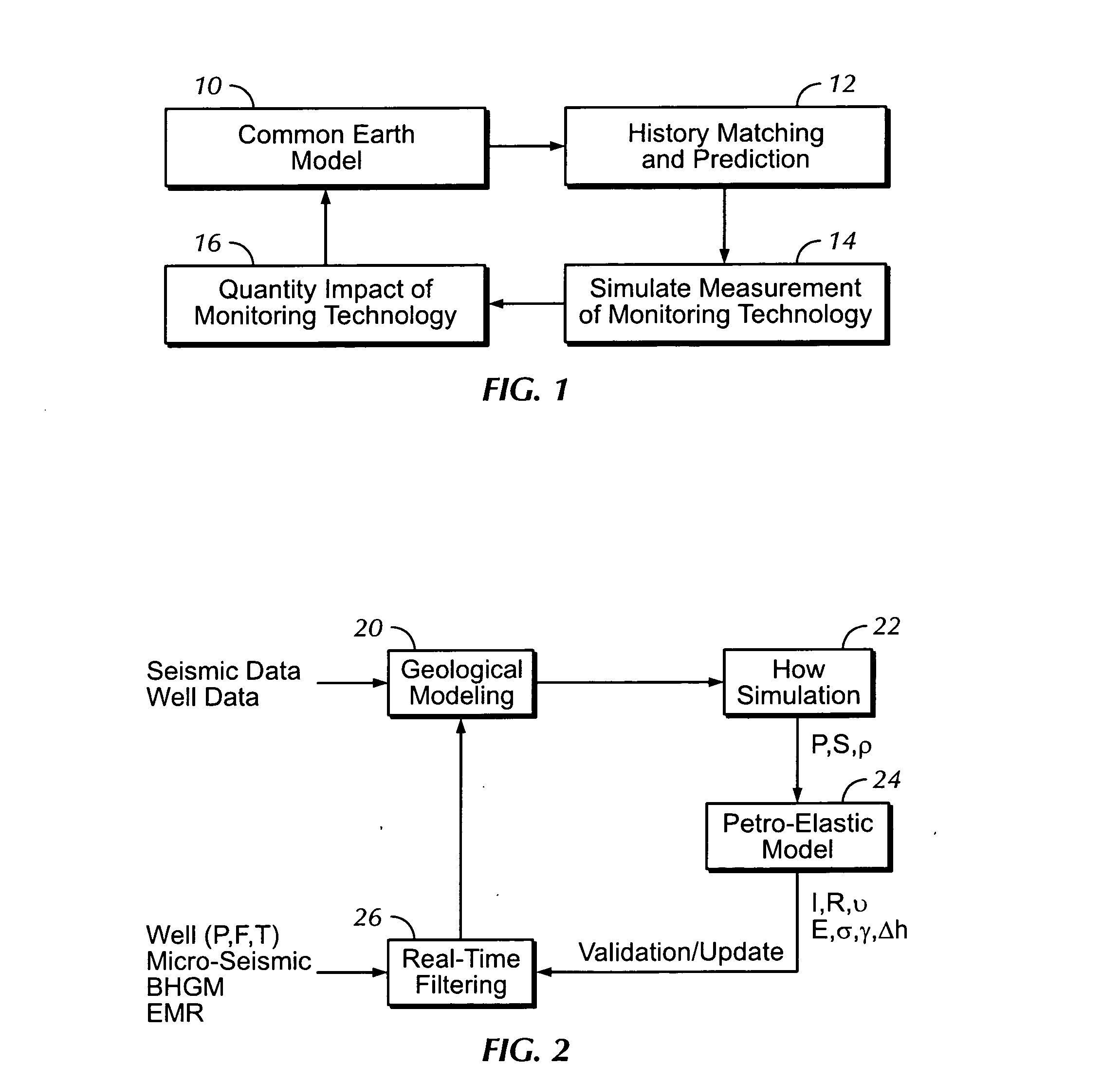
a technology of event monitoring and reservoir simulation, applied in seismology for waterlogging, instruments, reradiation, etc., can solve the problems of inability to accurately observe dimming, not all reservoirs respond equally well to direct measurement techniques, and data analysis has become a significant bottleneck

Active Publication Date: 2007-11-01
SAUDI ARABIAN OIL CO
View PDF18 Cites 44 Cited by
  • Summary
  • Abstract
  • Description
  • Claims
  • Application Information

AI Technical Summary

Benefits of technology

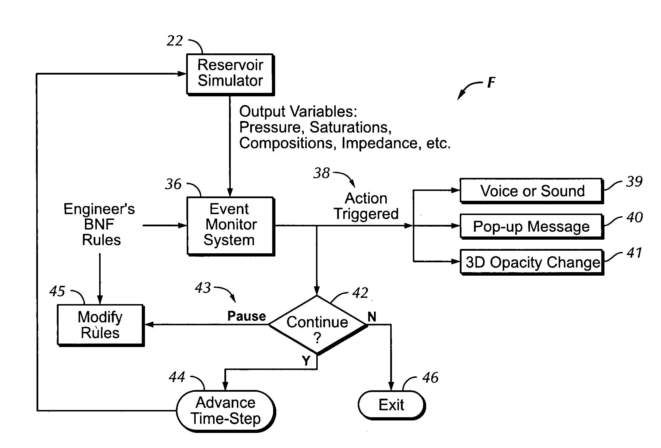
[0014] Briefly, the present invention provides a new and improved computer-implemented method of analysis of simulation results of a subsurface hydrocarbon reservoir. The method includes the steps of generating predicted values of properties of fluids in the volume of the reservoir. Event monitoring rules are then applied to the generated predicted values of the volume of the reservoir to detect whether specif

Problems solved by technology

The analysis of multi-million-cell reservoir simulation results has been a relatively new challenge to the petroleum industry.
With multi-million-cell reservoir simulation, however, data analysis has become a significant bottleneck when conventional monitoring techniques have been used.
As reservoir monitoring technologies have been applied in the last 10 years, it has become apparent that not all reservoirs respond equally well to these direct measurement techniques.
But in the case of giant reservoirs, such dimming may take many years to be observable with precision.
Furthermore, this change can only be confidently established in areas with good seismic signal quality.
Many reservoirs, for example in the Middle East, have a number of seismic data quality challenges that make 4D seismic of limited applicability and uncertain success.
This increases the effective stress (which is the difference between overburden confining stress and pore pressure) and the subsequent rock deformation can produce cracks detectable by seismograms at wellbore stations.

Method used


Image

  • Automated event monitoring system for online reservoir simulation
  • Automated event monitoring system for online reservoir simulation
  • Automated event monitoring system for online reservoir simulation

Examples


examples

[0212] Sound Talk(“Event condensate_dropout at cell”,Cell_Location) [0213] This would speak out a message like “Event condensate dropout at cell 14,20,5”

[0214] Sound Talk(“Event condensate_dropout at well”,Well Name) [0215] This would speak out a message like “Event condensate dropout at well Producer-15”

[0216] (37): Haptic_Clause is available for possible use as a triggered action.

[0217] (38): Graphics Opacity (Number).

[0218] This triggered action uses graphics instead of sound. A translucent opacity number (in the argument Number) will be applied to all cells in the reservoir to fade away except those that satisfied the condition, which should be revealed at fall strength. The rationale is to direct the attention of the engineer to the specific areas that satisfy the condition so that they are clearly visible in the 3D display, with everything else being visibly diminished or fading into an imperceptible background.

[0219] (39): Message (STRING, Event_Location_Info).

[0220] This...

example

[0221] Message (“Warning: Event water_breakthrough at cell”,Cell_Location) This would bring up a message box with the text “Warning: Event water_breakthrough at cell 30,40,20”

[0222] Using the BNF rule syntax as described above, an engineer can query the state of any of reservoir surveillance variables inside the simulator at any time. For example, the reservoir pressure displayed in FIG. 5 is of special practical importance to the engineer because any pressure at a well lower than the dew-point-pressure will result in “condensate drop-out”, which is the formation of condensate in the well. This reduces the gas flow performance and is, therefore, a condition the engineer must monitor carefully. Such an event would be monitored as follows (for a gas reservoir where the dew-point pressure is 6000 psi), as follows:

EventCloseToDewPointPressure AlwaysAt_Well (All_Wells, 1)Find_All Where ((PRESSURE 0.1))Sound Talk (“Pressure below 6000 at well”, Well_Name)End Event

[0223] Once significant...

example 1

[0228]

EventCloseToDewPointPressure AlwaysAt_Well (All_Wells, 1)Find_All Where ((PRESSURE 0.1))Sound Talk (“Pressure below 6000 at well”, Well_Name)End Event


PUM


Abstract

A computer-based system analyzes reservoir simulation results with a rule-based event monitor to trigger appropriate warnings in the event any of a number of applicable reservoir operation conditions is detected as likely to occur. The conditions may be automatically analyzed on multi-dimensional data during successive time steps to detect events indicated as needing attention or analysis and thus to alert reservoir engineers about operating conditions in the reservoir so that the engineers may make appropriate operational or simulation changes. The conditions may also be automatically analyzed in a batch processing mode of a set or subset of available time steps to detect and generate a log of events encountered that are indicated as needing attention or analysis.

Description

BACKGROUND OF THE INVENTION [0001] 1. Field of the Invention [0002] The present invention relates to computerized simulation of hydrocarbon reservoirs in the earth, and in particular to reservoir surveillance of producing oil and gas fields to monitor and calibrate changes in the fluid and rock properties of a reservoir. [0003] 2. Description of the Related Art [0004] The analysis of multi-million-cell reservoir simulation results has been a relatively new challenge to the petroleum industry. Recently, as disclosed in commonly-owned U.S. patent application Ser. No. 10 / 516,851, “A HIGHLY-PARALLEL, IMPLICIT COMPOSITIONAL RESERVOIR SIMULATOR FOR MULTI-MILLION CELL MODELS,” filed Aug. 12, 2004 (S. A. Docket No. 503); it has become possible to simulate giant datasets within practical time limits. With computer power making reservoir size and cell numbers less of a problem, the capability of human-machine interface to promptly interact and discern potential problem areas in the vast amoun...

Claims


Application Information

Patent Timeline
IPC IPC(8): G06G7/48
CPCG01V11/00
Inventor PITA, JORGE A.DOGRU, ALI H.AL-ZAMEL, NABIL M.
Owner SAUDI ARABIAN OIL CO
Learn More