Communication System for Use in Communication Between Communication Equipment by Using Ip Protocol

Inactive Publication Date: 2007-11-01
PANASONIC CORP
View PDF4 Cites 48 Cited by
  • Summary
  • Abstract
  • Description
  • Claims
  • Application Information

AI Technical Summary

Problems solved by technology

However, because of a rapid increase in the number of equipments connected to the Internet, global IP addresses tend to be insufficient.
However, the private IP address is not unique in the entire Internet and not permitted to be used in the Internet.
However, a restriction that a different equipment connected to the Internet cannot be freely connected to the equipment connected to the LAN and having the private IP address at desired time is imposed on the NAT technique.
For an end user unfamiliar with the IP address, there is such a problem that the setting contents are complicated.
Further, if the global IP address of the router apparatus is dynamically allocated by PPP (Point-to-Point Protocol) or DHCP (Dynamic Host Configuration Protocol), there is such a problem that it is difficult for the user to grasp the address and impossible for the user to specify the connection destination.
In other words, the static NAT function has a first problem that it is impossible to connect, to the equipment connected to the LAN and having only the private IP address, another equipment via the Internet without any user's static NAT setting in the router apparatus and user's search for the WAN side dynamic address of the router apparatus.
On the other hand, if the equipment connected to the LAN and having only the private IP address does not set the static NAT table of the router apparatus that includes the UPnP-IGD function in advance, another equipment connected to the Internet cannot directly operate the UPnP-IGD function of the router apparatus via the Internet.
Due to this, there is such a problem that it is impossible to start a connection from the equipment connected to the Internet to the equipment connected to the LAN and having only the priva

Method used


Image

  • Communication System for Use in Communication Between Communication Equipment by Using Ip Protocol
  • Communication System for Use in Communication Between Communication Equipment by Using Ip Protocol
  • Communication System for Use in Communication Between Communication Equipment by Using Ip Protocol

Examples


first embodiment

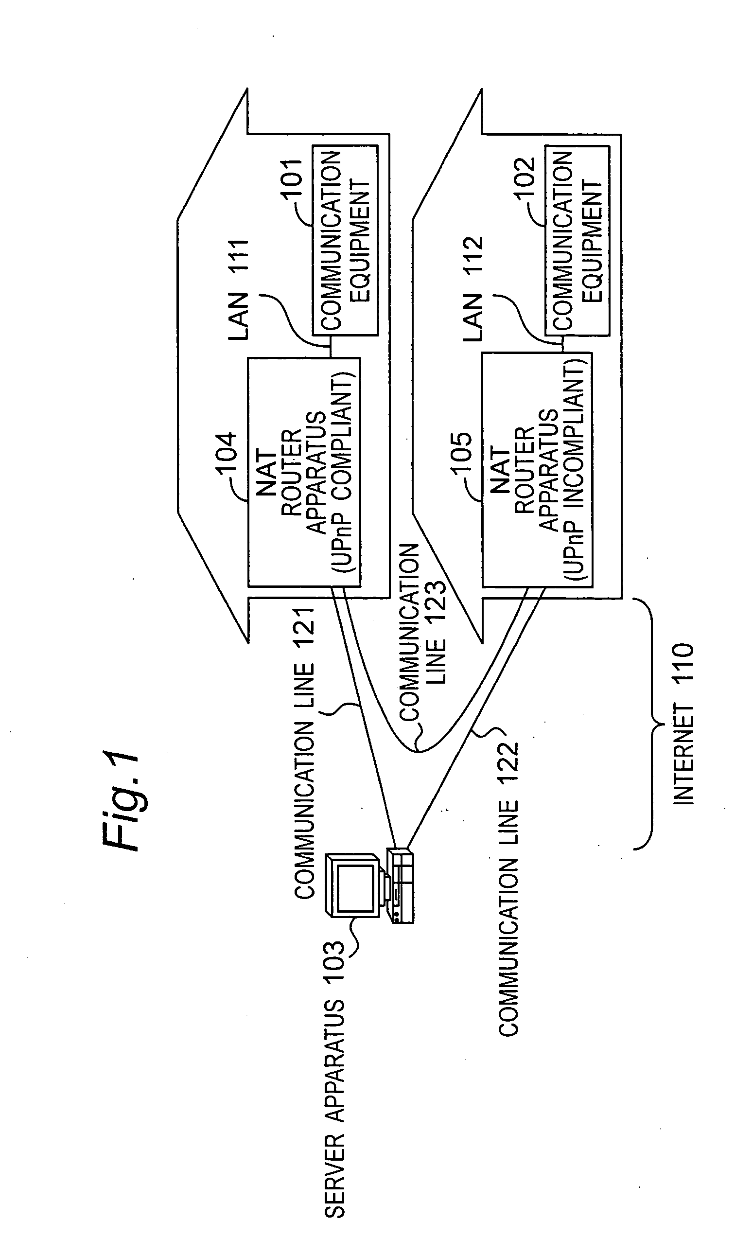
[0355] A communication system according to a first embodiment will be described hereinafter with reference to the drawings. FIG. 1 is a block diagram of a configuration of a communication system in which equipment or apparatuses are connected to each other via networks according to the present embodiment. A communication equipment 101 is connected to a NAT router (hereinafter, referred to as “a router apparatus”) 104 operating as a UPnP-IGD via a LAN 111. A WAN side port of the router apparatus 104 is connected to the Internet (WAN) 110. In a manner similar to that of above, a communication equipment 102 is connected to a NAT router (hereinafter, referred to as “a router apparatus”) 105 that does not include any function such as the UPnP-IGD via a LAN 112. A WAN side port of the router apparatus 105 is connected to the Internet (WAN) 110. Accordingly, the communication equipment 101 is connected to the Internet 110 via the LAN 111 and the router apparatus 104. The communication equi...

second embodiment

[0415]FIG. 8 is a sequence diagram showing a communication sequence according to a second embodiment of the present invention. The present embodiment is characterized in that a communication system similar to that of FIG. 1 operates, it is unnecessary to register, in advance, waiting and reception capability information on each of the communication equipments, and in that the request acceptance side communication equipment 101 decides the waiting and receiving side communication equipment and the connection side communication equipment.

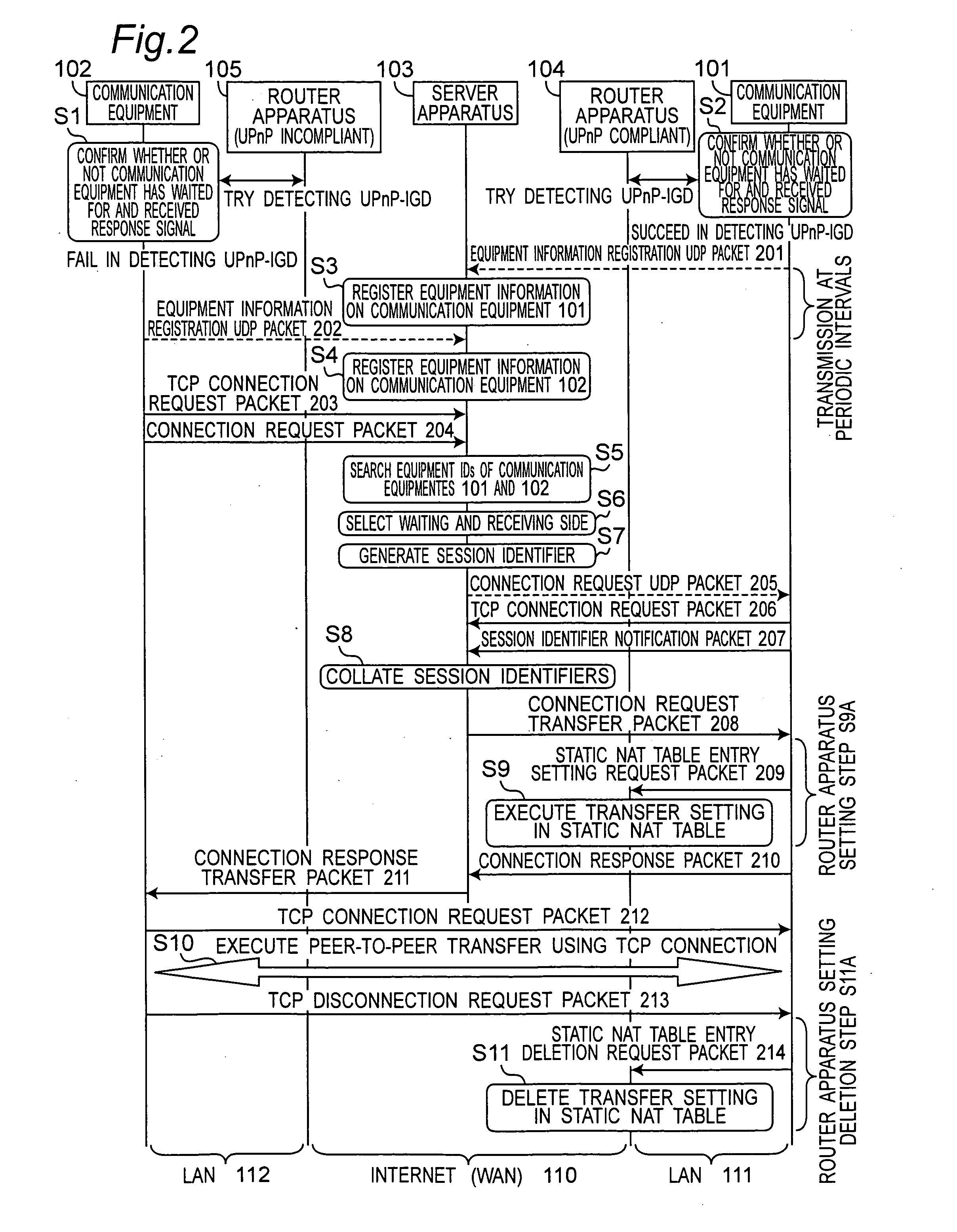
[0416] In the first embodiment, the server apparatus 103 selects the waiting and receiving side communication equipment at step S6 shown in FIG. 2. However, the embodiments of the present invention are not limited to the case in which the server apparatus 103 selects the waiting and receiving side communication equipment. One of a request issuance side communication equipment 102 and the request acceptance side communication equipment 101 may select ...

third embodiment

[0437]FIG. 11 is a sequence diagram showing a communication sequence according to the third embodiment of the present invention. The present embodiment is characterized in that that a communication system similar to that of FIG. 1 operates, it is unnecessary to register, in advance, waiting and reception capability information on each of the communication equipments, and in that the request issuance side communication equipment 102 decides the waiting and receiving side communication equipment and the connection side communication equipment.

[0438] The communication system will be described with reference to the communication sequence of FIG. 11. In a manner similar to that of FIG. 8, communication equipments 101 and 102 register equipment information on the communication equipments 101 and 102 in an equipment information database apparatus (not shown) of the server apparatus 103 by using equipment information registration UDP packets 201a and 202a, respectively. In addition, the co...


PUM


Abstract

A server apparatus selects one of communication equipment that has a waiting and reception capability as a waiting and receiving side communication equipment based on waiting and reception capability information on the respective communication equipments, and selects another communication equipment as a connection side communication equipment. The waiting and receiving side communication equipment sets a router apparatus connected to the waiting and receiving side communication equipment so that the router apparatus receives a signal having a destination of waiting and receiving address information, and transfers the received signal to the waiting and receiving side communication equipment. The connection side communication equipment transmits a packet having the destination of the waiting and receiving address information to the waiting and receiving side communication equipment.

Description

TECHNICAL FIELD [0001] The present invention relates to a communication system that adopts an IP protocol. More specifically, the present invention relates to a communication system for allowing a peer-to-peer communication to be held between a communication equipment connected to a network such as the Internet via, for example, a LAN and a different communication equipment connected to the network via another LAN, to a server apparatus and a communication equipment that constitute the communication system, and to a communication method. The present invention also relates to a program that includes steps for the communication method, and a recording medium that stores the program. BACKGROUND ART [0002] In recent years, due to establishment of a broadband environment for an xDSL, an optical fiber cable, and the like, the Internet has been rapidly spreading not only in companies but also in homes. In addition, it is possible to connect home electric appliances such as a television rec...

Claims


Application Information

Patent Timeline
IPC IPC(8): G06F15/00G06F13/00G06F21/44H04L9/08H04L12/46H04L45/741
CPCH04L67/14H04L12/28H04L12/46
Inventor TAKECHI, HIDEAKINAKATSUKA, MONTAKUNIHIRA, TADASHIKATO, NAONORI
Owner PANASONIC CORP
Why Eureka
Try Eureka