Thermal head and printing device

a printing device and thermal head technology, applied in printing and other directions, can solve the problems of increasing the power consumption of raising the temperature to the sublimation point, increasing the power consumption of printing at higher speeds, and so as to achieve the effect of improving thermal efficiency, reducing the heat storage capacity of glass layers, and easy radiation

Inactive Publication Date: 2007-11-08
SONY CORP
View PDF3 Cites 7 Cited by
  • Summary
  • Abstract
  • Description
  • Claims
  • Application Information

AI Technical Summary

Benefits of technology

[0019] In embodiment of the invention, by forming the groove section in the glass layer, it becomes difficult for the heat generated by the heat generation section to radiated to the glass layer side, thus the thermal efficiency can be improved. Further, in the embodiment of the invention, the heat storage capacity of the glass layer is reduced by providing the groove section, thus the heat can easily be radiated and the response is improved. From the facts described above, thermal efficiency and response can be improved in the invention. Further, according to the embodiment of the invention, by forming the groove section to have a width equal to or larger than the length of the heat generation section, the thickness of the both ends of the heat storage section facing the heat generation section and storing the heat is made smaller, thus the heat radiation from the both ends can be suppressed to further improve the thermal efficiency. Further, in the embodiment of the invention, the thickness of the both ends of the heat storage section is made further smaller by making the curvature radius of the both sides of the protruding section smaller than the curvature radius in the central portion thereof, thus the thermal efficiency can further be improved. Thus, in the embodiments of the invention, high speed printing with low power consumption can be achieved.

Problems solved by technology

In this thermal transfer printing device, power consumption becomes larger when printing at higher speed because the thermal head needs to be rapidly heated to a high temperature.
Therefore, it is difficult particularly in home-use-printing devices to increase printing speeds while achieving lower power consumption.
However, in the thermal head 100, since the thermal energy in the heat generation section 103a is radiated to the side of the ceramic substrate 101 to easily reduce the temperature, the power consumption in raising the temperature to the sublimation point increases, thus making the thermal efficiency worse.
According to the thermal head 100, although the preferable response can be obtained, thermal efficiency is degraded, and accordingly, it is required to heat the heat generating section 103a for a long period of time to obtain a desired depth, which causes large power consumption and makes it difficult to improve the printing speed while achieving low power consumption.
Thus, in the thermal head 110, since the response is degraded even with the improved thermal efficiency, it is difficult to increase the printing speed.

Method used


Image

  • Thermal head and printing device
  • Thermal head and printing device
  • Thermal head and printing device

Examples


Embodiment Construction

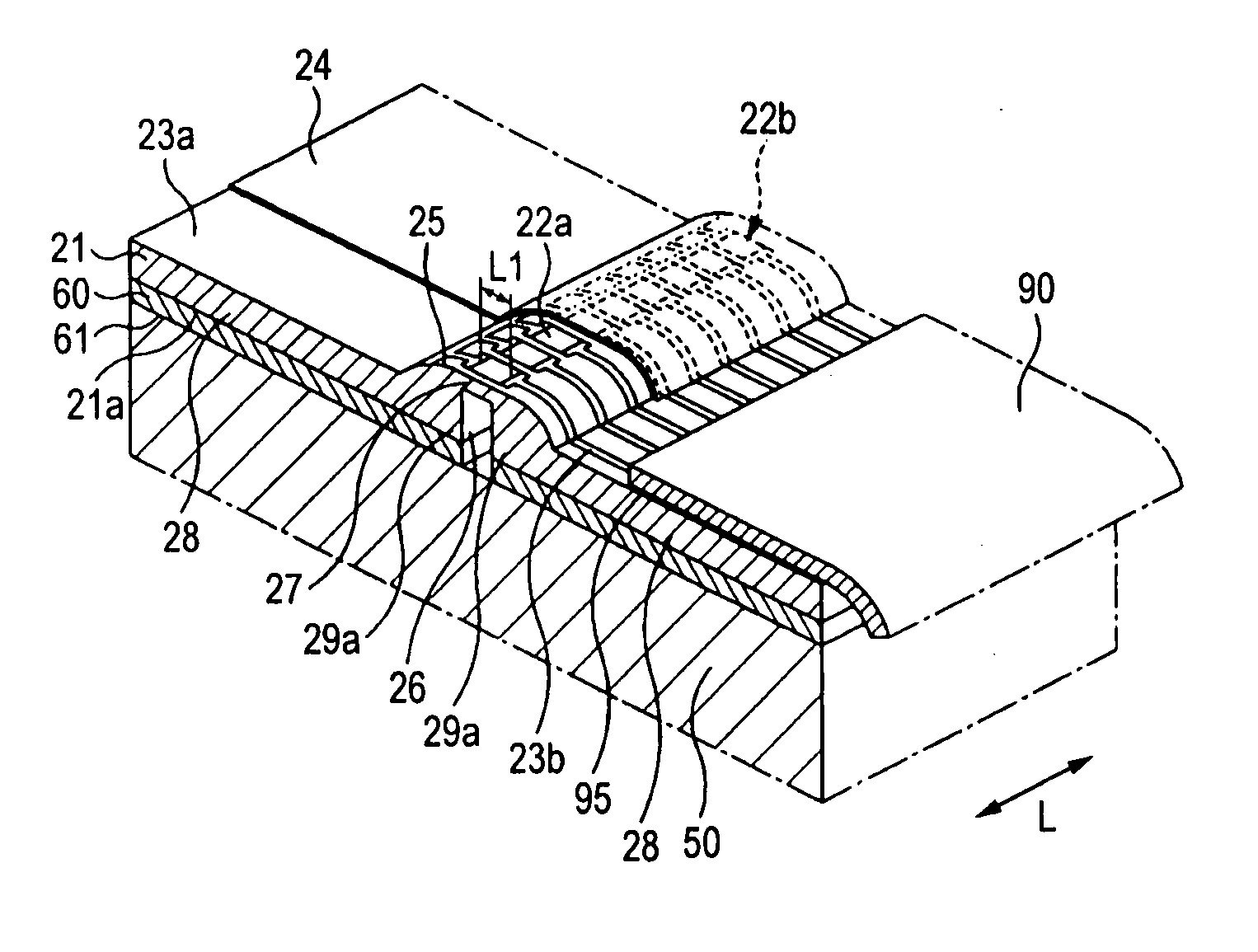
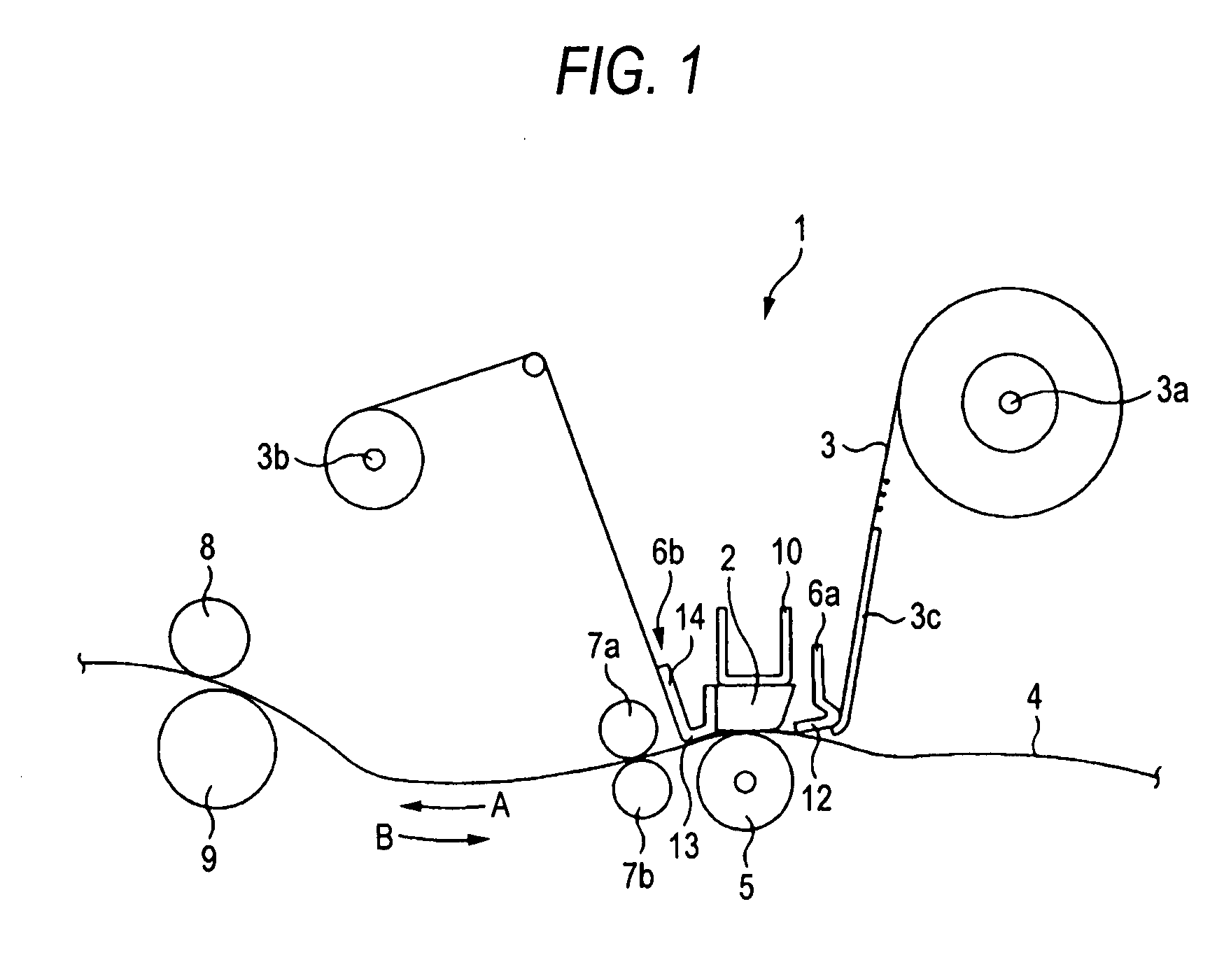
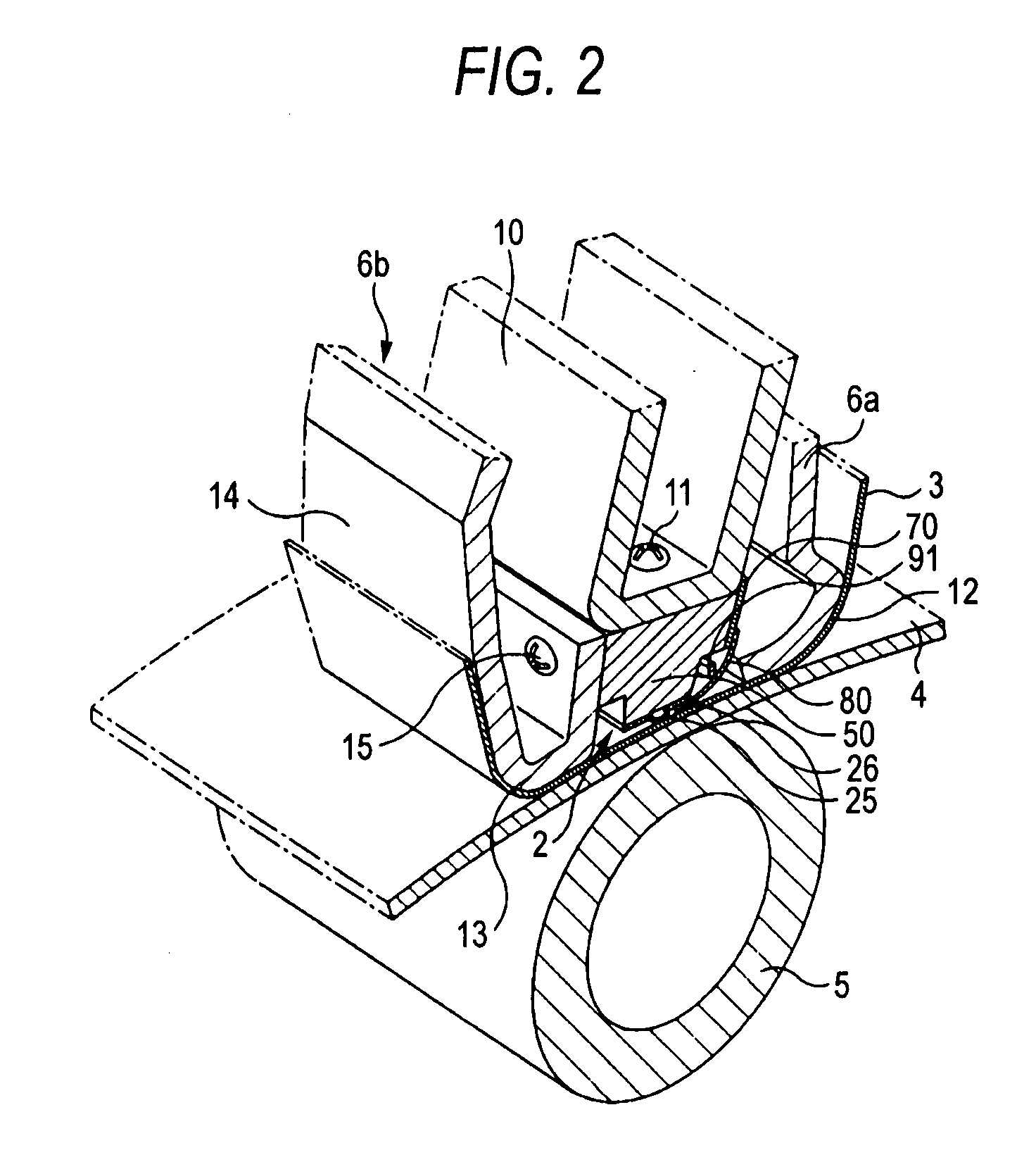
[0042] Hereinafter, a thermal transfer printing device implementing a thermal head applying an embodiment of the invention will be explained in detail with reference to the accompanying drawings.

[0043] A thermal transfer printing device 1 (hereinafter referred to as a printing device 1) shown in FIG. 1 is a dye sublimation printer for sublimating a color material of an ink ribbon to thermal-transfer the color material to a print medium, and uses a thermal head 2 applying an embodiment of the invention as a recording head. The printing device 1 applies thermal energy generated by the thermal head 2 to the ink ribbon 3, thereby sublimating the color material of the ink ribbon 3 to thermal-transfer it to the print medium 4, thus printing color images or characters. The printing device 1 is a home-use printing device, and is able to print on objects of, for example, a post card size as the print medium 4.

[0044] The ink ribbon 3 used here is formed of a long resin film, and is housed i...


PUM


Abstract

A thermal head includes a glass layer having a protruding section formed on one surface and a concave groove section formed on the other surface facing the protruding section, a heat generation resistor provided on the protruding section, and a pair of electrodes provided to both sides of the heat generation resistor, and a part of the heat generation resistor exposed between the pair of electrodes is defined as a heat generation section, the protruding section has a smaller curvature radius in both sides than a curvature radius in a central portion, and a width of the groove section is one of equal to and larger than a length of the heat generation section.

Description

CROSS REFERENCES TO RELATED APPLICATIONS [0001] The present invention contains subject matter related to Japanese Patent Application JP 2006-075661 filed in the Japan Patent Office on Mar. 17, 2006, the entire contents of which being incorporated herein by reference. BACKGROUND OF THE INVENTION [0002] 1. Technical Field [0003] The present invention relates to a thermal head and a printing device for thermal-transferring a color material on an ink ribbon to a print medium. [0004] 2. Related Art [0005] As a printing device for printing images or characters on a print medium, there is a thermal transfer printing device (hereinafter simply referred to as a printing device) which sublimates a color material forming a ink layer provided to one surface of an ink ribbon to thermal-transfer the color material to a print medium, thereby printing color images or characters. The printing device is provided with a thermal head for thermal-transferring the color material on the ink ribbon to the ...

Claims


Application Information

Patent Timeline
Patent Type & Authority Applications(United States)
IPC IPC(8): B41J2/34
CPCB41J2/33585B41J2/3357B41J2/335
Inventor KOYAMA, NOBORUKARIYA, IZUMIYANASE, MITSUOMORIKAWA, TORU
Owner SONY CORP
Why Eureka
Try Eureka