Electronic system having resistors serially connected

a technology of resistors and circuits, which is applied in the direction of electric devices, propulsion by batteries/cells, transportation and packaging, etc., can solve the problems of difficult to radiate the heat generated and received in each of the resistors, and achieve the effect of easy and rapid radiating of heat generated and received

Active Publication Date: 2012-02-09
DENSO CORP
View PDF4 Cites 4 Cited by
  • Summary
  • Abstract
  • Description
  • Claims
  • Application Information

AI Technical Summary

Benefits of technology

[0011]With this structure of the electronic system, when a discharged current flows through the resistance circuit, heat is generated in each of the resistors, and each of the resistors receives heat generated in the other resistors. In this case, heat received in each of the resistors located at positions different from the ends of the series of resistors is larger than heat received in any of the resistors located on the ends of the series of resistors. In this case, each of the two resistors located on the ends of the series of resistors can easily and rapidly radiate the heat generated and received in the resistor. In contrast, it is difficult to radiate the heat generated and received in each of the resistors located at positions different from the ends of the series of resistors. Therefore, assuming that resistance values of the resistors of the resistance circuit are the same, the temperature increase in the resistors located at positions different from the ends of the series of resistors becomes larger than the temperature increase in the resistors located on the ends of the series of resistors.
[0012]In the present invention, each resistor located at a position different from the ends of the series of resistors is set to have a resistance value lower than resistance values of the two resistors located on the respective ends of the series of resistors of the resistance circuit. In this case, electric power consumed in each resistor located at a position different from the ends of the series of resistors becomes smaller than electric power consumed in any of the resistors located on the ends of the series of resistors. Therefore, heat generated in each resistor from which it is difficult to radiate heat becomes smaller than heat generated in any resistor from which heat is easily radiated.
[0013]Accordingly, the temperature increase in each resistor from which it is difficult to radiate heat can be suppressed, and the increase in temperatures of the resistors of the resistance circuit can be suppressed within an allowable range.
[0014]Further, because the temperature increase in the resistors is suppressed, it is not required to receive heat in a thermal conductive metal, formed of a metallic material, being in contact with the resistors. Accordingly, even when a high voltage is applied to the resistance circuit, the insulation distance among the resistors can be reliably secured.

Problems solved by technology

In contrast, it is difficult to radiate the heat generated and received in each of the resistors located at positions different from the ends of the series of resistors.

Method used


Image

  • Electronic system having resistors serially connected
  • Electronic system having resistors serially connected
  • Electronic system having resistors serially connected

Examples


first embodiment

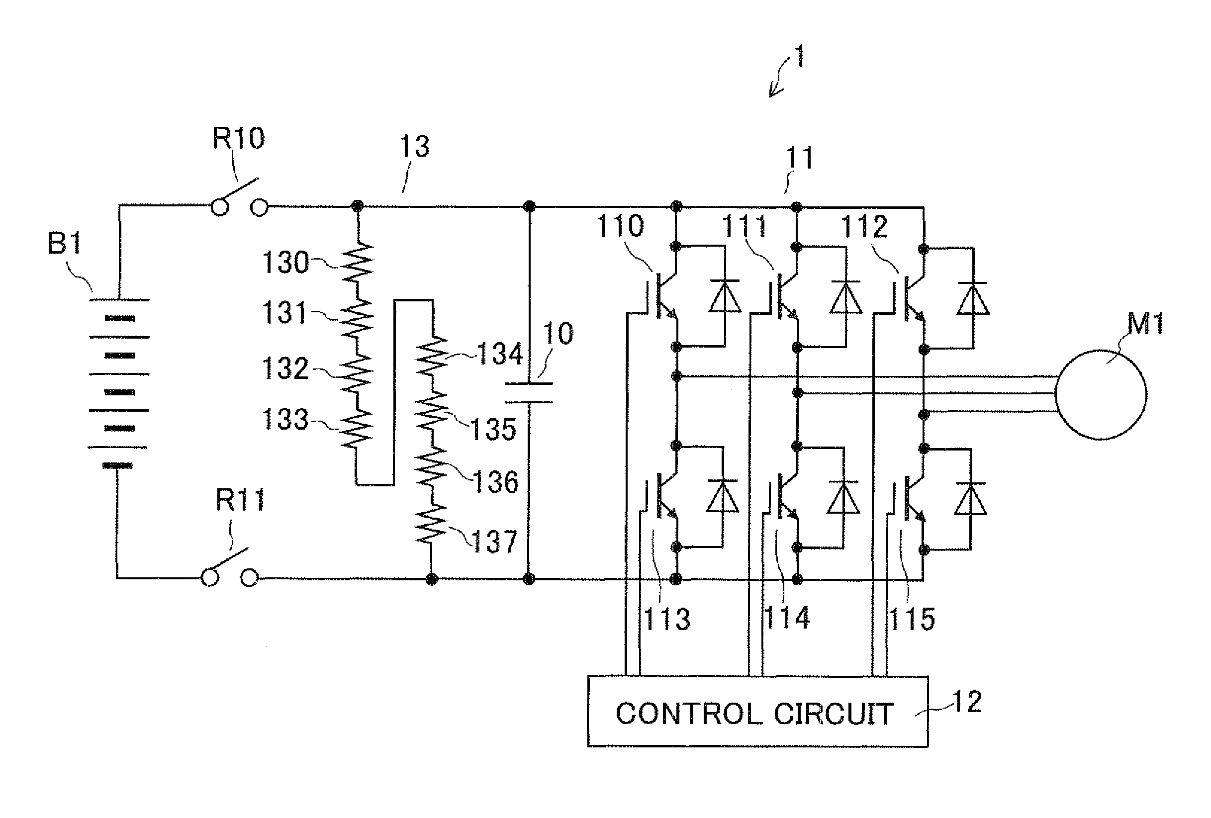
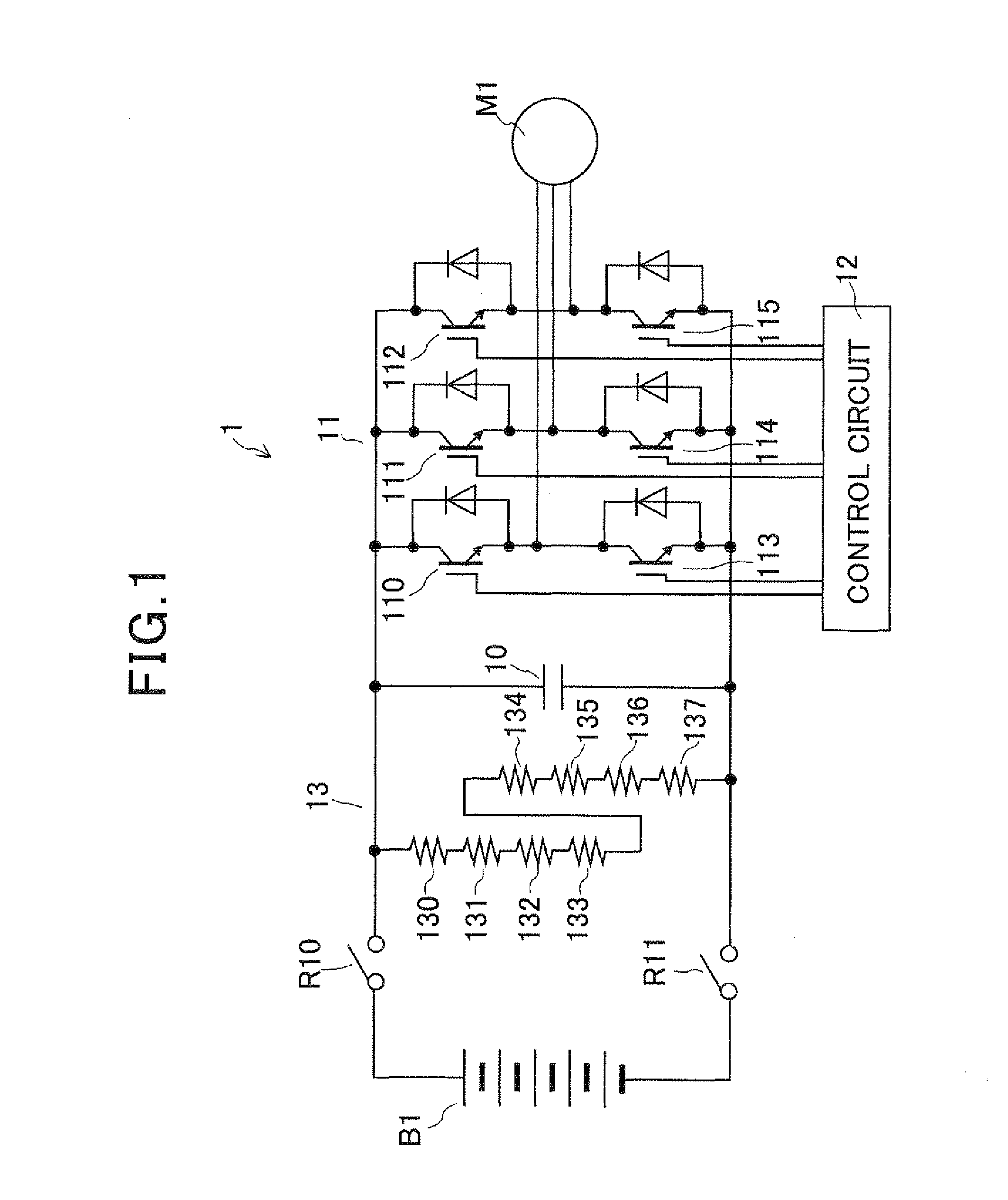
[0021]FIG. 1 is a circuit view of a motor control system representing an electronic system according to the first embodiment. As shown in FIG. 1, a motor control system 1 converts a high direct current (dc) voltage (e.g., 288V) outputted from a high voltage battery B1 (i.e., a direct current source) into a three-phase alternating current (ac) voltage and applies this ac voltage to a vehicle driving motor M1 to control the motor M1. The battery B1 is insulated from the body of the vehicle. The control system 1 has a smoothing capacitor 10, an inverter circuit 11, a control circuit 12 and a resistance circuit 13.

[0022]The capacitor 10 accumulates electric charge supplied from the battery B1 to smooth the high dc voltage of the battery B1. The first end of the capacitor 10 is connected with the positive electrode of the battery B1 through a relay R10, while the second end of the capacitor 10 is connected with the negative electrode of the battery B1 through a relay R11.

[0023]The invert...

second embodiment

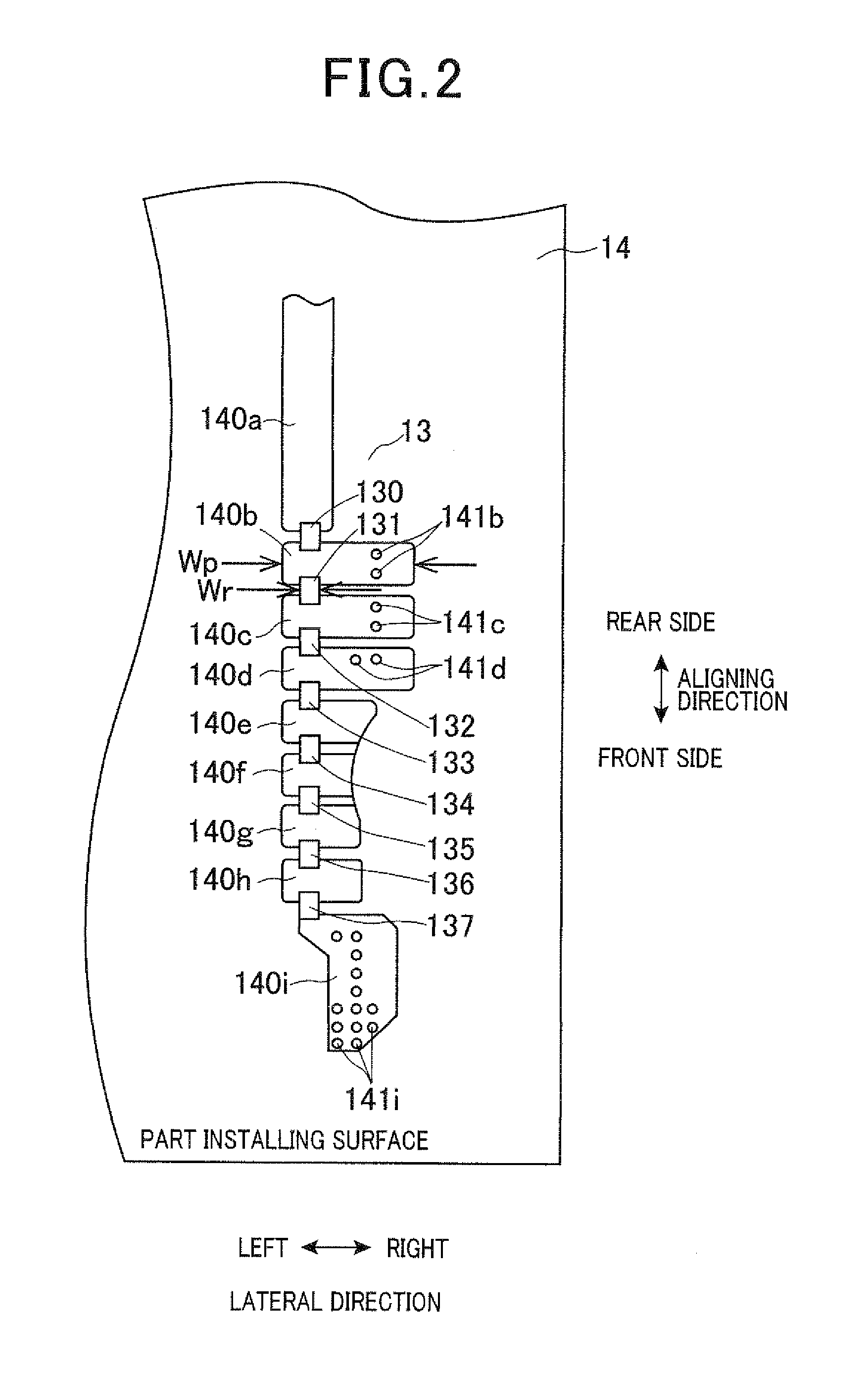
[0065]FIG. 4 is an enlarged view of patterned wires serially connecting resistors of the circuit 13 on the part installing surface of the substrate 14 according to the second embodiment, while FIG. 5 is an enlarged view of a patterned member (indicated by a dotted line) disposed on the soldering surface of the substrate 14, when being seen from the part installing surface, according to the second embodiment. The front and rear sides in the aligning direction and the right and left in the lateral direction are defined for convenience of explanation.

[0066]As shown in FIG. 4 and FIG. 5, the control system 1 having the capacitor 10, the inverter circuit 11 and the control circuit 12 has a resistance circuit 23 in place of the resistance circuit 13. The circuit 23 has a plurality of patterned wires 240a, 240b, 240c, 240d, 240e, 240f, 240g, 240h and 240i disposed on the part installing surface of the substrate 14 while aligning the wires 240a to 240i in a line at equal intervals from the ...


PUM


Abstract

An electronic system has a capacitor that smoothes voltage of a direct current source, a resistance circuit that discharges charge of the capacitor, and an inverter circuit that converts the smoothed voltage into a three-phase ac voltage and applies this ac voltage to a motor. The resistance circuit has resistors and patterned wires disposed on a substrate such that the wires serially connect the resistors to discharge charge of the capacitor. The resistors are aligned in a straight line. The resistors located at positions different from ends of the series of resistors have resistance values lower than resistance values of the resistors located at respective ends of the series of resistors. More preferably, as the position of one resistor approaches the center of the series of resistors, the resistor is set at a lower the resistance value.

Description

CROSS-REFERENCE TO RELATED APPLICATION[0001]This application is based upon and claims the benefit of priority of the prior Japanese Patent Application 2010-176302 filed on Aug. 5, 2010, so that the contents of which are incorporated herein by reference.BACKGROUND OF THE INVENTION[0002]1. Field of the Invention[0003]The present invention relates to an electronic system having a resistance circuit in which a plurality of resistors are serially connected with each other.[0004]2. Description of Related Art[0005]As an electronic system capable of suppressing the increase in temperatures of electronic parts, an electronic circuit device has been disclosed in Published Japanese Patent First Publication No. 2010-73943. This device is provided with an electronic circuit chip, a base substrate and a thermal conductivity member. The chip is disposed on the substrate. The conductivity member is disposed between the chip and the substrate while being in contact with the chip and the substrate. T...

Claims


Application Information

Patent Timeline
Patent Type & Authority Applications(United States)
IPC IPC(8): B60L3/00
CPCB60L3/0084B60L11/1803B60L15/20B60L2240/36Y02T10/7275B60L2270/20Y02T10/644Y02T10/7005B60L2240/423Y02T10/72B60L50/51Y02T10/64Y02T10/70
Inventor ITOU, AKITO
Owner DENSO CORP
Why Eureka
Try Eureka