Battery charger and battery charging method

a battery charger and charging method technology, which is applied in the field of battery charger and battery charging method for charging a battery, can solve the problems of reducing affecting the service life of the battery, so as to achieve the effect of suppressing the temperature ris

Inactive Publication Date: 2007-06-12
MAKITA CORP
View PDF50 Cites 3 Cited by
  • Summary
  • Abstract
  • Description
  • Claims
  • Application Information

AI Technical Summary

Benefits of technology

[0008]TheOne object of the present invention has been made to solveis to overcome the above-stated problems and ananother object of this invention is to provide a battery charger and a battery charging method capable of appropriately charging a battery in a short time while suppressing the temperature rise ofavoiding overheating the battery which is being suppressedduring charging.

Problems solved by technology

If the temperature of the battery becomes high bydue to the generated heat, the electrodes and separators of the cells within the battery will deteriorate and battery life iswill be shortened.
Due to this, it ishas been impossible to quickly charge thea nickel metal hydride battery withusing high current as was previously done for the nickel cadmium battery stated abovebatteries.

Method used


Image

  • Battery charger and battery charging method
  • Battery charger and battery charging method
  • Battery charger and battery charging method

Examples


first embodiment

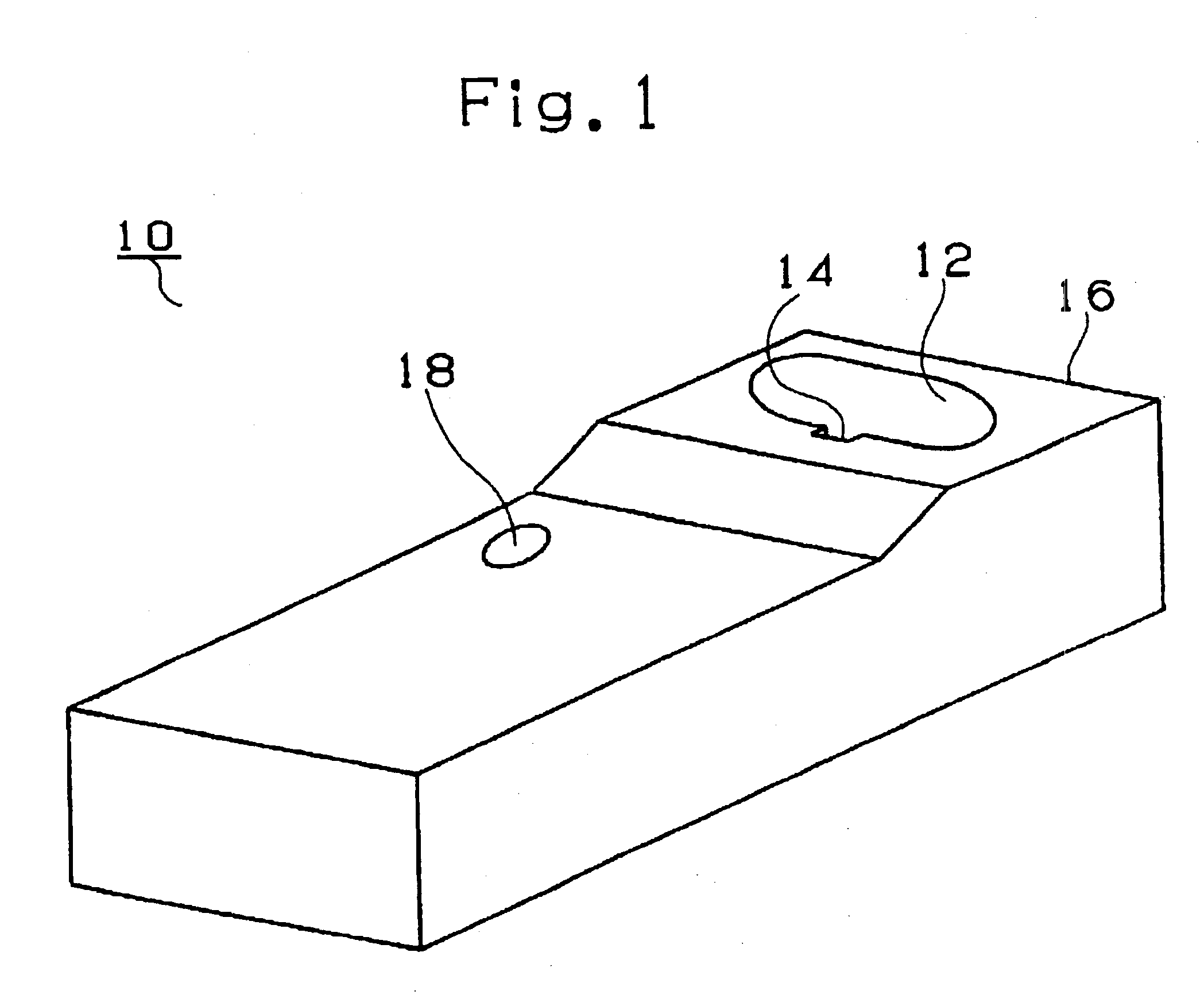
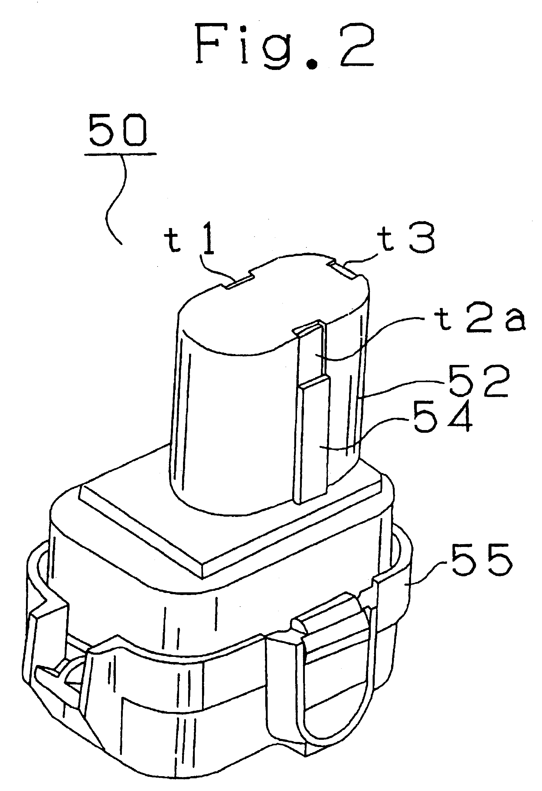
[0065]FIG. 1 shows a battery charger 10inof the present invention, FIG. 2 shows a battery pack 50 charged by the battery charger 10 and FIG. 3 shows a battery-powered drill 70 driven by the battery pack 50.

[0066]As shown in FIG. 2, the battery pack 50 containing a nickel metal hydride battery cell consists of a generally cylindrical fitted part 52 and a generally prismatic base 55. A key-shaped key part 54 is formed on the side of the fitted part 52 and the first input terminal t1 connected to the positive electrode of the battery, the second input terminal t2a connected to the negative electrode thereof and the third terminal t3 connected to a temperature sensor consisting of a thermistor are arranged on the upper portion of the fitted part 52.

[0067]As shown in FIG. 1, the battery charger 10 charging the battery packs 50 is provided with a fitting hole 12 into which the fitted part 52 of the battery pack 50 is fitted. A keyway 14 for introducing the key part 54 of the fitted part 5...

second embodiment

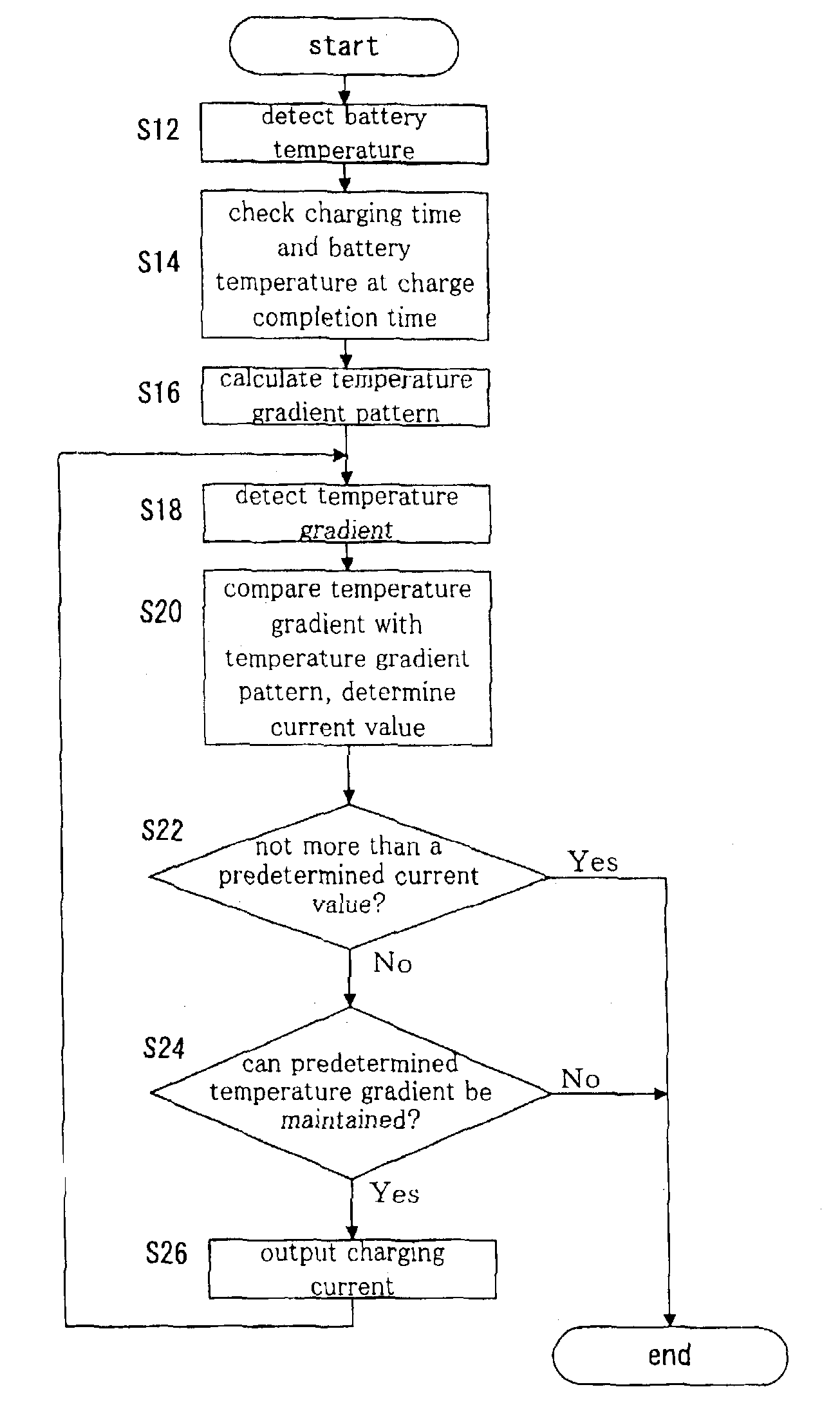
[0092]The specific charge control of the battery charger in the second embodiment will be described with reference to FIG. 12.

[0093]First, the control section 136 detects the temperature of the battery pack 150 from the temperature detecting section 138 (in S112). Here, it is assumed that outside air temperature is 20° C. and battery temperature is 25° C. Next, charging time and battery temperature at the time of the completion of charge are checked (in S114). In this case, when charging time is 20 minutes, the final temperature rise value of 35 degrees (30 deg+5 deg) is obtained. Thereafter, a temperature rise pattern is calculated (in S116).

[0094]The control section 136 differentiates the difference between the temperature value inputted from the previous temperature detecting section and the temperature value inputted this time and obtains a temperature rise value (in S118). The control section 136 then compares this detected temperature rise value with the temperature rise patte...

third embodiment

[0098]Next, a battery charging method in the third embodiment according to the present invention will be described with reference to FIGS. 13 to 15.

[0099]In the second embodiment stated above, the battery charger holds the charging time and final battery temperature rise values shown in FIG. 10. In the third embodiment, by contrast, a battery pack holds border lines each indicating the final temperature when battery charge is completed at the lowest temperature described above with reference to FIG. 9. Namely, the final temperature which the battery reaches when it is completed with charge differs depending on the voltage of the battery pack (the number of battery cells), the type of the battery (nickel metal hydride batteries may have different characteristics), the heat radiation characteristics of the battery pack and the like. Due to this, the battery charger in this embodiment is intended to be capable of charging any battery pack most efficiently by making the battery pack hol...


PUM

PropertyMeasurementUnit
temperatureaaaaaaaaaa

Abstract

A temperature rise pattern is retrieved from charging time based on the difference between a battery temperature at the beginning of battery charge and a target temperature value which a battery is intended to reach (in S116). The battery is charged while adjusting a current value so that a temperature rise value becomes the temperature rise pattern (in S118 and S120). Thus, by optimizing the temperature rise pattern, it is possible to charge the battery so that the temperature at the time of the completion of battery charge becomes the target temperature value (the lowest temperature value).

Description

[0001]This is a reissue of U.S. Pat. No. 6,204,640, issued on Mar. 20, 2001.BACKGROUND OF THE INVENTION[0002]1. Field of the Invention[0003]The present invention relates to a battery charger and a battery charging method for charging a battery and particularly relates to a battery charger and a battery charging method suited for charging a battery, such as a nickel metal hydride battery, which emits high heat while being charged.[0004]2. Discussion of the Prior Art[0005]Presently, a chargeable battery which can be repeatedly used for the power supply of, for example, a power tool is used.[0006]A nickel cadmium battery is popular as a battery for the power tool, and a battery charger for quickly charging the battery by applying high current thereto is used. Specifically, the battery is quickly charged in about 20 minutes and a power tool can be continuously used by switching a battery to that which has been charged.[0007]The present inventor of the present invention studiedhas invest...

Claims


Application Information

Patent Timeline
Patent Type & Authority Patents(United States)
IPC IPC(8): H01M10/46H02J7/10H01M10/44H02J7/00H02J7/04
CPCH02J7/0091H01M10/443Y02E60/10H02J7/007194
Inventor SAKAKIBARA, KAZUYUKI
Owner MAKITA CORP
Why Eureka
Try Eureka