

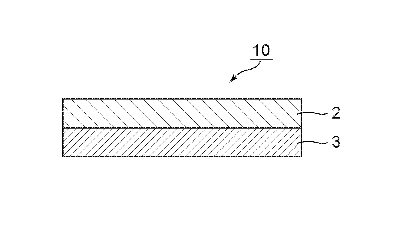
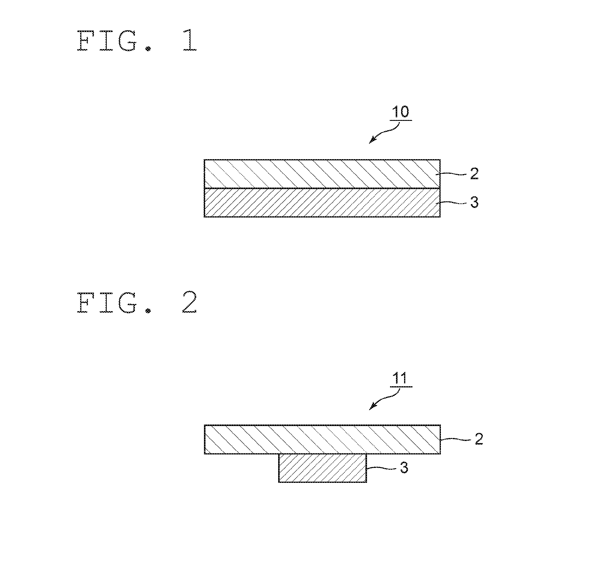
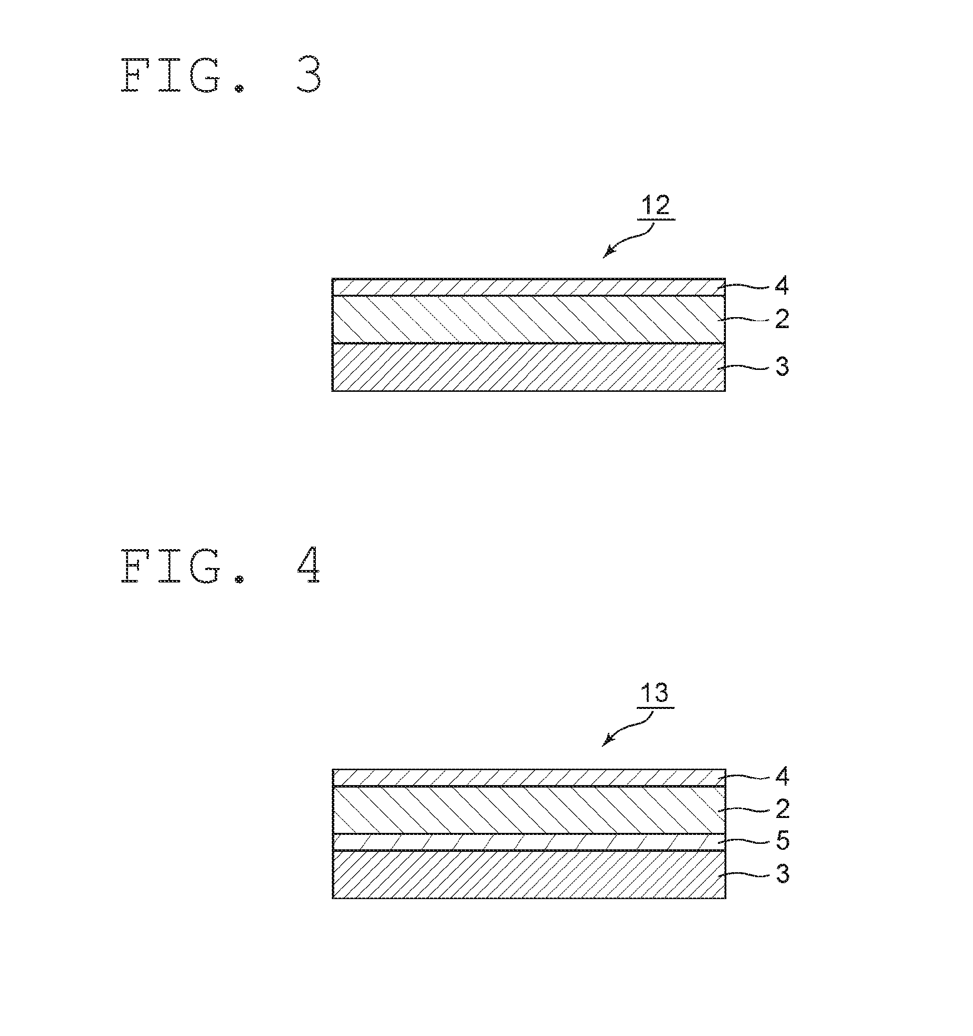
Radiant heat conduction-suppressing sheet
a technology of radiation heat conductivity and heat conductivity, which is applied in the direction of electrical equipment construction details, other domestic objects, transportation and packaging, etc., can solve the problems of small distance between each electronic part and the housing, user gets a low-temperature burn, and heat spot occurs so as to achieve satisfactorily suppress the occurrence of heat spot on the surface of the housing, efficient reflection, and the effect of reducing the effect of heat spo
- Summary
- Abstract
- Description
- Claims
- Application Information
AI Technical Summary
Benefits of technology
Problems solved by technology
Method used
Image

Examples
production example 1
Preparation of Mixed Syrup 1
[0145]A reactor equipped with a cooling tube, a temperature gauge, and a stirrer was fed with 173.2 parts by weight of a monomer solution formed of 2-ethylhexyl acrylate (manufactured by TOAGOSEI CO., LTD., hereinafter abbreviated as “2EHA”) as an ethylenically unsaturated monomer, 100 parts by weight of ADEKA (trademark) Pluronic L-62 (molecular weight: 2,500, manufactured by ADEKA CORPORATION, polyether polyol) as polyoxyethylene polyoxypropylene glycol, and 0.014 part by weight of dibutyltin dilaurate (manufactured by KISHIDA CHEMICAL Co., Ltd., hereinafter abbreviated as “DBTL”) as a urethane reaction catalyst. To the stirred mixture were added dropwise 12.4 parts by weight of hydrogenated xylylene diisocyanate (manufactured by Takeda Pharmaceutical Co., Ltd., TAKENATE 600, hereinafter abbreviated as “HXDI”), and the resultant mixture was subjected to a reaction at 65° C. for 4 hours. It should be noted that the usage of a polyisocyanate component and...
production example 2
Preparation of Mixed Syrup 2
[0146]A reactor equipped with a cooling tube, a temperature gauge, and a stirrer was fed with 173.2 parts by weight of a monomer solution formed of IBXA as an ethylenically unsaturated monomer, 100 parts by weight of ADEKA (trademark) Pluronic L-62 (molecular weight: 2,500, manufactured by ADEKA CORPORATION, polyether polyol) as polyoxyethylene polyoxypropylene glycol, and 0.014 part by weight of DBTL as a urethane reaction catalyst. To the stirred mixture were added dropwise 12.4 parts by weight of HXDI, and the resultant mixture was subjected to a reaction at 65° C. for 4 hours. It should be noted that the usage of a polyisocyanate component and a polyol component in terms of NCO / OH (equivalent ratio) was 1.6. After that, 5.6 parts by weight of HEA were added dropwise, and the mixture was subjected to a reaction at 65° C. for 2 hours. Thus, a hydrophilic polyurethane-based polymer / ethylenically unsaturated monomer mixed syrup was obtained. The resultant...
example 1
[0147]100 Parts by weight of the hydrophilic polyurethane-based polymer / ethylenically unsaturated monomer mixed syrup 1 obtained in Production Example 1 were homogeneously mixed with 11.9 parts by weight of 1,6-hexanediol diacrylate (a product available under the trade name “NK Ester A-HD-N” from Shin Nakamura Chemical Co., Ltd.) (molecular weight: 226), 47.7 parts by weight of urethane acrylate (hereinafter abbreviated as “UA”) (molecular weight: 3,720) having an ethylenically unsaturated group at each of both terminals, in which both terminals of polyurethane synthesized from polytetramethylene glycol (hereinafter abbreviated as “PTMG”) and isophorone diisocyanate (hereinafter abbreviated as “IPDI”) were treated with HEA, as a reactive oligomer, 0.48 part by weight of diphenyl(2,4,6-trimethylbenzoyl)phosphine oxide (a product available under the trade name “Lucirin TPO” from BASF), 0.95 part by weight of a hindered phenol-based antioxidant (a product available under the trade name...
PUM
| Property | Measurement | Unit |
|---|---|---|
| wavelength | aaaaa | aaaaa |
| pore diameter | aaaaa | aaaaa |
| pore diameter | aaaaa | aaaaa |
Abstract
Description
Claims
Application Information