Electronic system having resistors serially connected
a technology of resistors and circuits, which is applied in the direction of electric devices, propulsion by batteries/cells, transportation and packaging, etc., can solve the problems of difficult to radiate the heat generated and received in each of the resistors, and achieve the effect of easy and rapid radiating of heat generated and received
- Summary
- Abstract
- Description
- Claims
- Application Information
AI Technical Summary
Benefits of technology
Problems solved by technology
Method used
Image
Examples
first embodiment
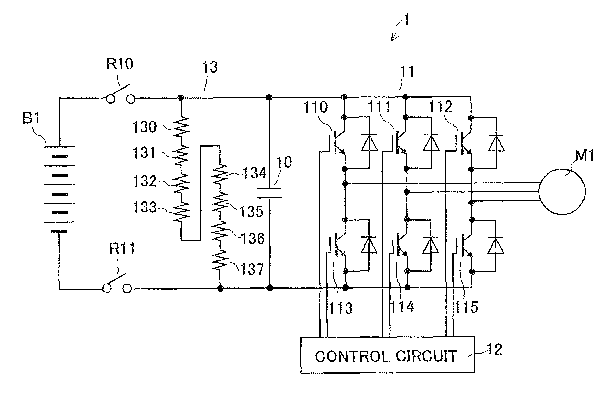
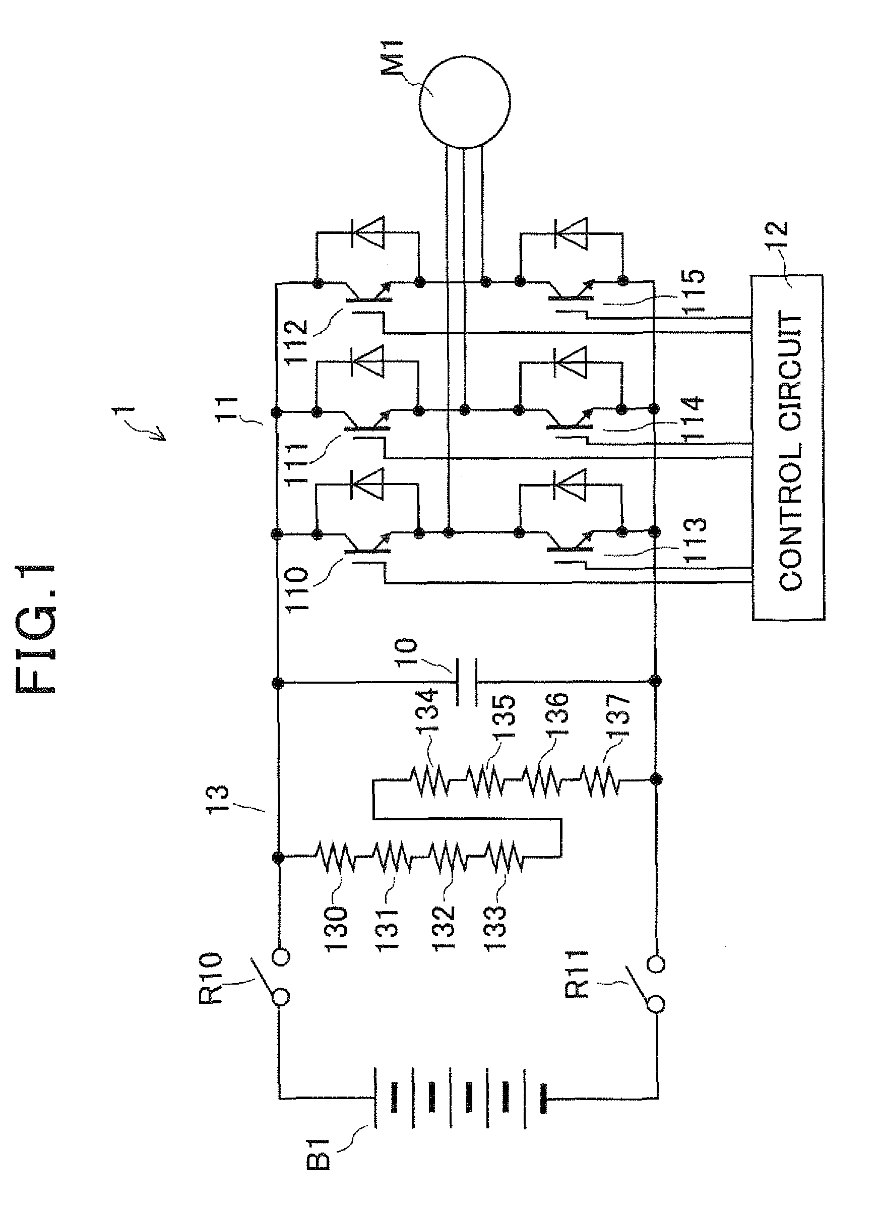
[0022]FIG. 1 is a circuit view of a motor control system representing an electronic system according to the first embodiment. As shown in FIG. 1, a motor control system 1 converts a high direct current (dc) voltage (e.g., 288V) outputted from a high voltage battery B1 (i.e., a direct current source) into a three-phase alternating current (ac) voltage and applies this ac voltage to a vehicle driving motor M1 to control the motor M1. The battery B1 is insulated from the body of the vehicle. The control system 1 has a smoothing capacitor10, an inverter circuit 11, a control circuit 12 and a resistance circuit 13.
[0023]The capacitor 10 accumulates electric charge supplied from the battery B1 to smooth the high dc voltage of the battery B1. The first end of the capacitor 10 is connected with the positive electrode of the battery B1 through a relay R10, while the second end of the capacitor 10 is connected with the negative electrode of the battery B1 through a relay R11.
[0024]The inverte...
second embodiment
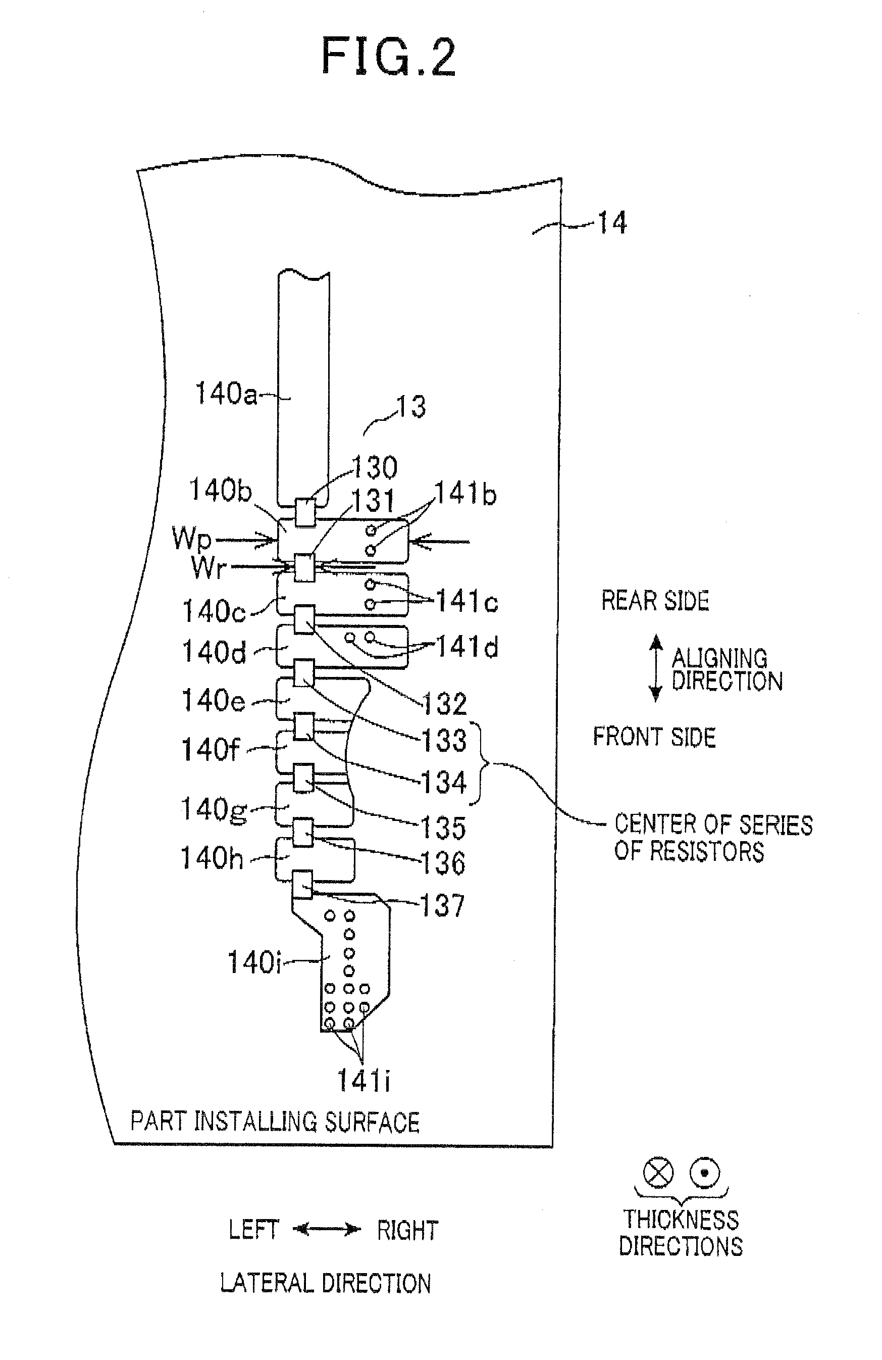
[0067]FIG. 4 is an enlarged view of patterned wires serially connecting resistors of the circuit 13 on the part installing surface of the substrate 14 according to the second embodiment, while FIG. 5 is an enlarged view of a patterned member (indicated by a dotted line) disposed on the soldering surface of the substrate 14, when being seen from the part installing surface, according to the second embodiment. The front and rear sides in the aligning direction and the right and left in the lateral direction are defined for convenience of explanation.
[0068]As shown in FIG. 4 and FIG. 5, the control system 1 having the capacitor 10, the inverter circuit 11 and the control circuit 12 has a resistance circuit 23 in place of the resistance circuit 13. The circuit 23 has a plurality of patterned wires 240a, 240b, 240c, 240d, 240e, 240f, 240g, 240h and 240i disposed on the part installing surface of the substrate 14 while aligning the wires 240a to 240i in a line at equal intervals from the ...
PUM
 Abstract
Description
Claims
Application Information
 - R&D
- Intellectual Property
- Life Sciences
- Materials
- Tech Scout
- Unparalleled Data Quality
- Higher Quality Content
- 60% Fewer Hallucinations
Browse by: Latest US Patents, China's latest patents, Technical Efficacy Thesaurus, Application Domain, Technology Topic, Popular Technical Reports.
© 2025 PatSnap. All rights reserved.Legal|Privacy policy|Modern Slavery Act Transparency Statement|Sitemap|About US| Contact US: help@patsnap.com


