Turbine blade tip cap

a turbine blade and tip cap technology, applied in the direction of machines/engines, liquid fuel engines,foundry moulding apparatus, etc., can solve the problems of rotor blades that require replacement, minute holes in airfoil surfaces, and “repair fallout", so as to facilitate attachment and relieve stress

Inactive Publication Date: 2007-11-08
GENERAL ELECTRIC CO
View PDF18 Cites 35 Cited by
  • Summary
  • Abstract
  • Description
  • Claims
  • Application Information

AI Technical Summary

Benefits of technology

[0003] In an exemplary embodiment of this invention, replacement blades are provided that have a new tip cap configuration that eliminates the need for the platinum core support pins. More specifically, the cast-in tip cap design is eliminated so that both the radially inner and outer ends of the blades are open during casting. This means that the internal core support can be held at both ends of the blade, eliminating the need for internal core support pins. A discrete tip cap is then welded onto the outer end of the airfoil. To facilitate attachment, the outer end of the airfoil is provided with a peripheral shoulder on which a rimmed planar tip cap is seated and subsequently welded. An added benefit is that the welded tip cap also relieves stresses at the radially outer end of the blade. Further in this regard, the tip cap is supported and welded only about its peripheral edge, i.e., there is no underlying mid-span support.

Problems solved by technology

Some turbine components, such as rotor blades, have required replacement after one service interval (for example, three years) because of the inability to repair the component.
For some turbine blades, the limiting factor is the integral “cast-in” tip cap design of the blades which requires that the core support used in casting the blade be internally supported by many small platinum pins that extend through the blade airfoil.
If the pins are not precisely masked, the stripping chemical will melt the pins, leaving minute holes in the airfoil surfaces.
This leads to a problem known as “repair fallout” with as many as 25% of blades being disposed of rather than recoated.

Method used


Image

  • Turbine blade tip cap
  • Turbine blade tip cap
  • Turbine blade tip cap

Examples


Embodiment Construction

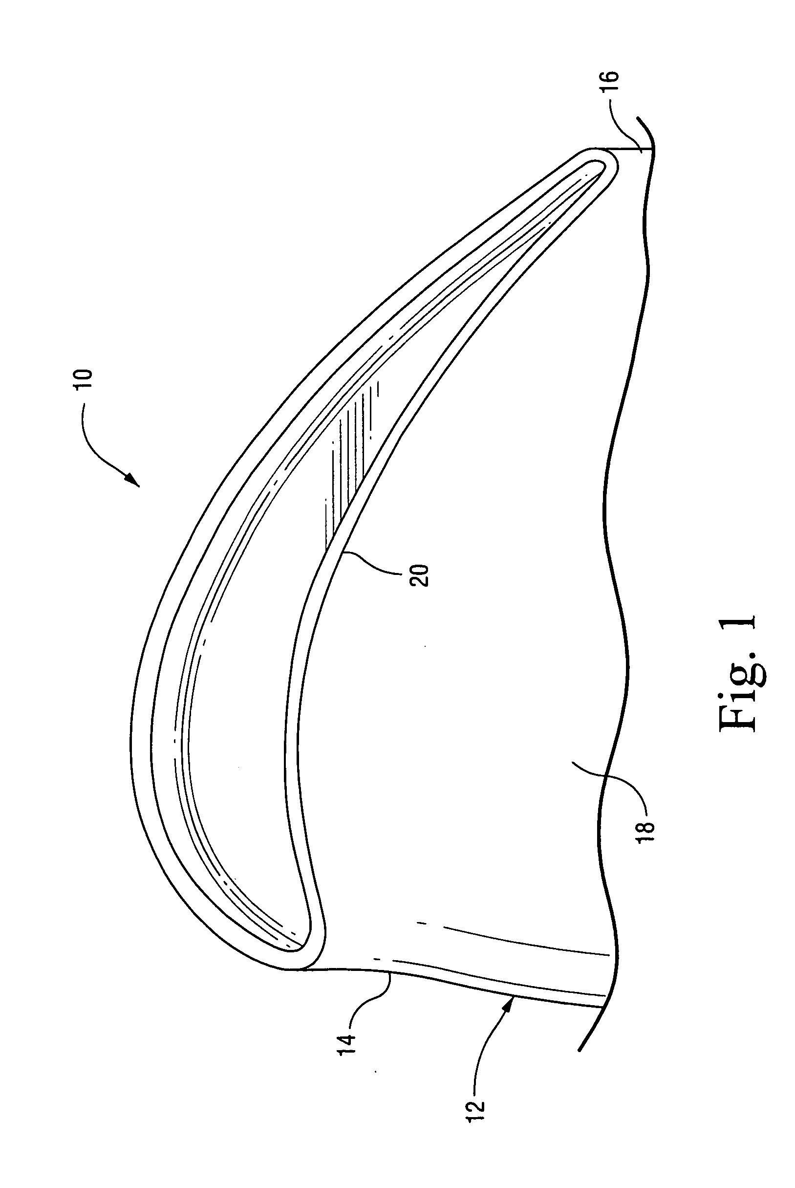
[0013]FIG. 1 illustrates a known turbine blade 10 having an airfoil portion 12 as defined by a leading edge 14, a trailing edge 16, a pressure side 18 and a suction side 20. The blade is formed with an integral, cast-in tip cap 22. In such blade designs, the use of internal core support pins (not shown) is required to provide the necessary support during casting, since it is not possible to hold the core support from the radially outer end of the blade. The ends of the core support pins extend through the airfoil and lie flush with the airfoil exterior surface. As indicated above, these support pins often fail, i.e., melt, during an airfoil coating-stripping process, particularly if not masked properly, leaving minute holes in the airfoil surfaces.

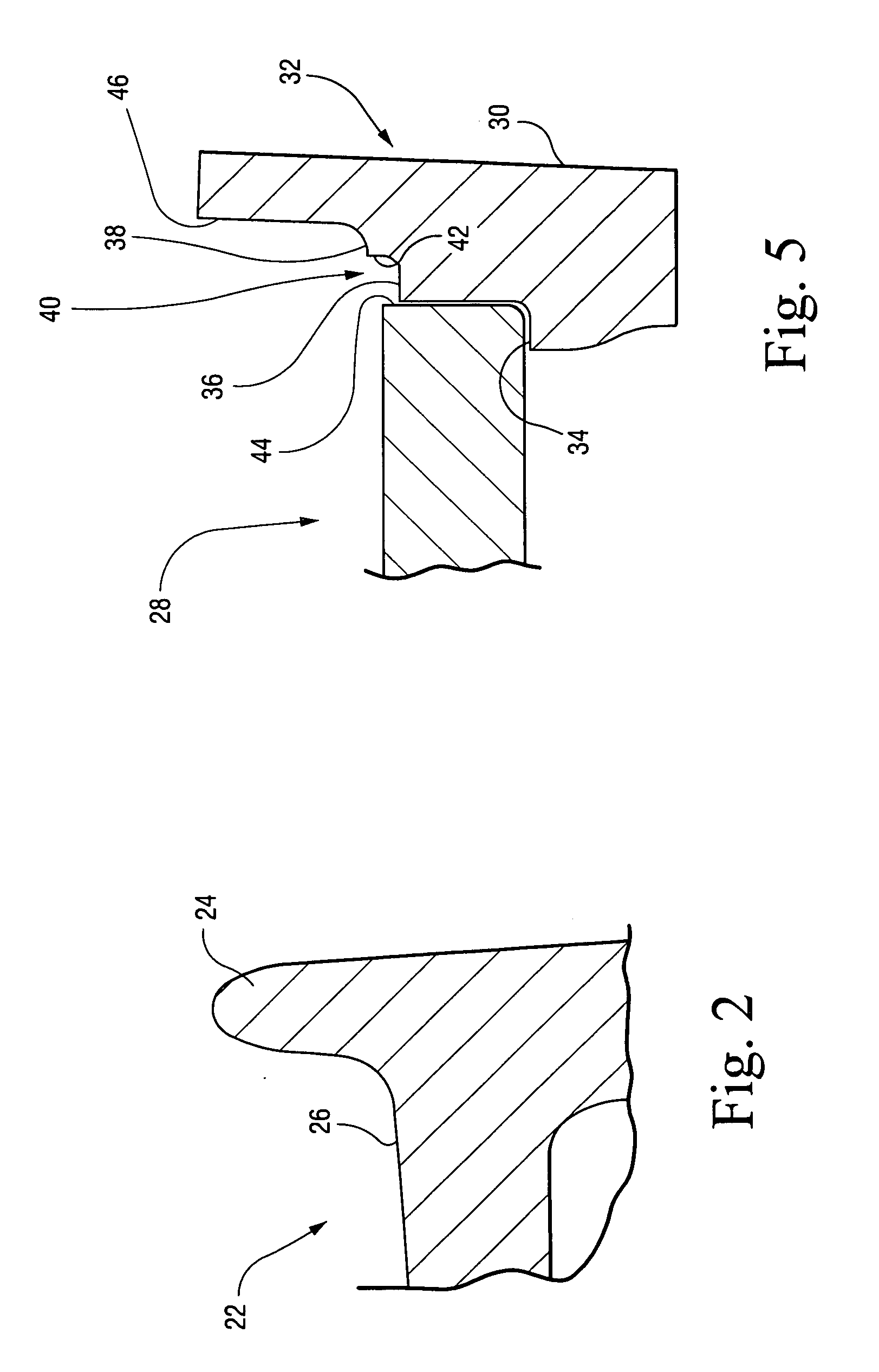
[0014]FIG. 2 shows an enlarged detail of the cast-in tip cap 22, with a peripheral rim 24 at the radially outer end of the airfoil portion 12, extending above or outwardly of the end closure portion 26 of the tip cap.

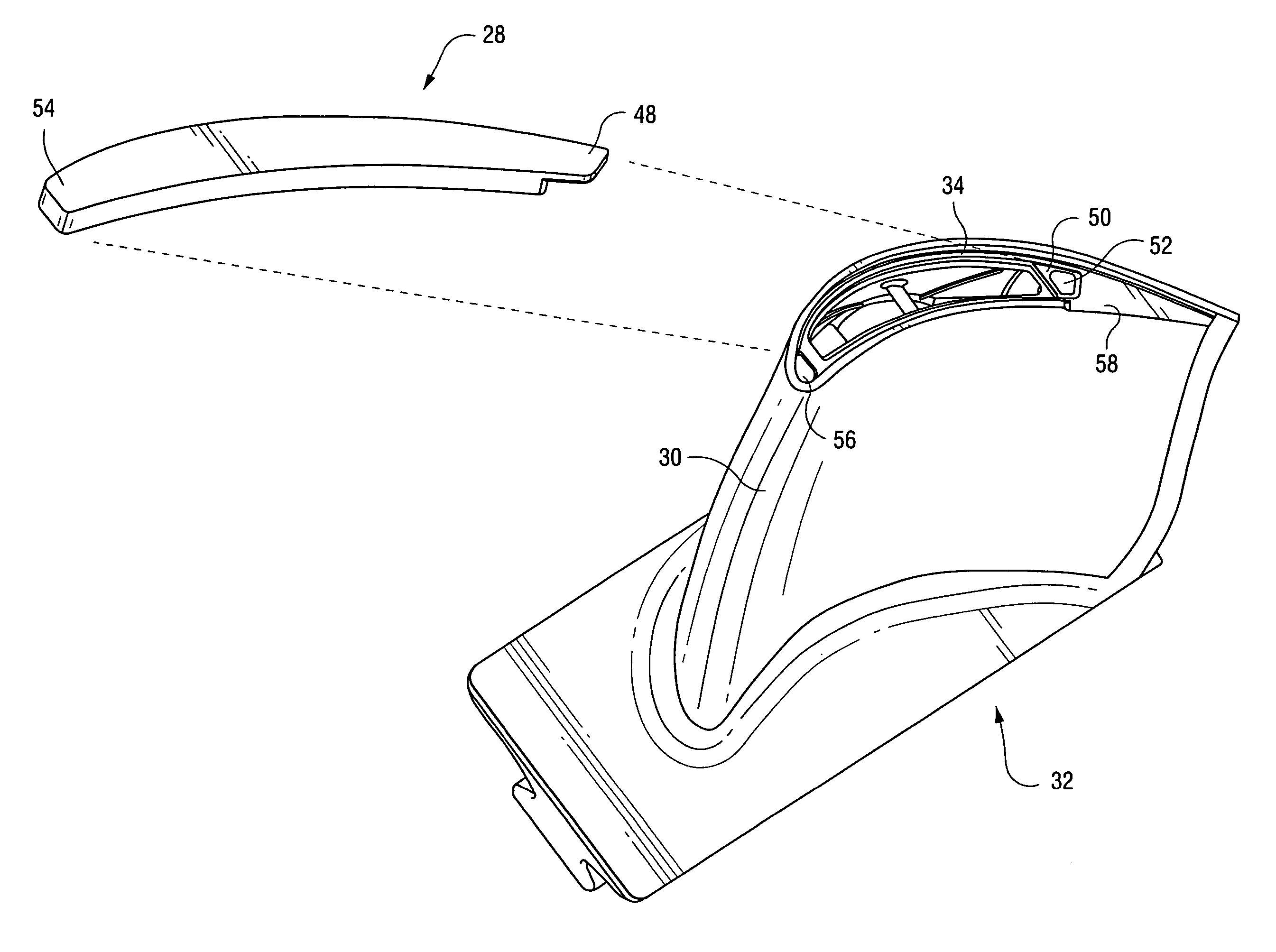
[0015]FIGS. 3-5 show...


PUM

PropertyMeasurementUnit
thicknessaaaaaaaaaa
angleaaaaaaaaaa
thicknessaaaaaaaaaa

Abstract

A method of manufacturing a turbine blade includes (a) supporting a turbine blade internal core support at opposite ends such that radially inner and outer ends of the turbine blade remain open during casting; (b) casting the blade including the airfoil portion, wherein the radially outer edge of the airfoil portion is inclined relative to horizontal; (c) machining the radially outer edge of the airfoil portion to form a peripheral shoulder about a radially outer opening in the airfoil portion; and (d) seating a tip cap on the peripheral shoulder and fixing the tip cap to the airfoil portion of the blade.

Description

BACKGROUND OF THE INVENTION [0001] This invention relates to turbine blade technology and, more specifically, to a replacement turbine blade having a discrete tip cap configuration that facilitates manufacture in a manner that increases blade life. [0002] Some turbine components, such as rotor blades, have required replacement after one service interval (for example, three years) because of the inability to repair the component. For some turbine blades, the limiting factor is the integral “cast-in” tip cap design of the blades which requires that the core support used in casting the blade be internally supported by many small platinum pins that extend through the blade airfoil. In the finished blade, therefore, the platinum pin faces are exposed, flush with the exterior airfoil surfaces. At the end of a service interval, blades are typically stripped and re-coated. The platinum pins have to be masked during the stripping process to prevent chemical attack on the platinum. If the pin...

Claims


Application Information

Patent Timeline
Patent Type & Authority Applications(United States)
IPC IPC(8): B64C27/46
CPCB23P6/002F01D5/147F05D2230/10B22C21/14F05D2230/21F01D5/20
Inventor SHADBOLT, SIMONPODMORE, NICKJORDAN, STEPHEN J.MURIITHI, KAHWAI G.THERMOS, ANTHONY C.WEBER, JOSEPH A.
Owner GENERAL ELECTRIC CO
Why Eureka
Try Eureka