Temporary Dental Prosthesis

a dental prosthesis and temporary technology, applied in dental prosthesis, dentistry, medical science, etc., can solve the problems of unsightly healing cup, undesirable psychological effect, and high undesirable effect, and achieve the effect of minimizing the transmission of external loads

Inactive Publication Date: 2007-11-08
L P M DENTAL DEV
View PDF11 Cites 36 Cited by
  • Summary
  • Abstract
  • Description
  • Claims
  • Application Information

AI Technical Summary

Benefits of technology

[0011] The present invention relates to a provisional or temporary substantially non-load bearing fixed dental prosthesis, comprising a prosthesis body and at least one interface adapted for mounting said prosthesis to at least one implant, wherein said prosthesis body is configured for substantially absorbing externally-applied loads acting on the prosthesis body and for minimizing transmission of such external loads to at least a said implant onto which said temporary prosthesis may be mounted.

Problems solved by technology

The healing cup does not have the appearance of a dental structure, nor does it function as such—in fact this is considered highly undesirable.
However, the healing cup itself is unsightly and may have an undesirable psychological effect of self-consciousness on many patients.
However, this type of procedure, though shorter than the conventional loading procedure and reducing the number of surgical interventions with respect thereto, carries potential risks of infection and of micromovement of the implant due to loads that may be applied to the healing cup when masticating, for example.
Further, the esthetically unappealing cup is visible for a considerable period.
While a shorter process than the one-step procedure, and while not involving the use of an unsightly healing cup, there is nevertheless a risk of infection, as well as of substantial micromovement of the implant, as the first prosthesis is directly loaded by the regular forces in the intraoral cavity, such as mastication for example, before the implant has been fully anchored in place.

Method used


Image

  • Temporary Dental Prosthesis
  • Temporary Dental Prosthesis
  • Temporary Dental Prosthesis

Examples


first embodiment

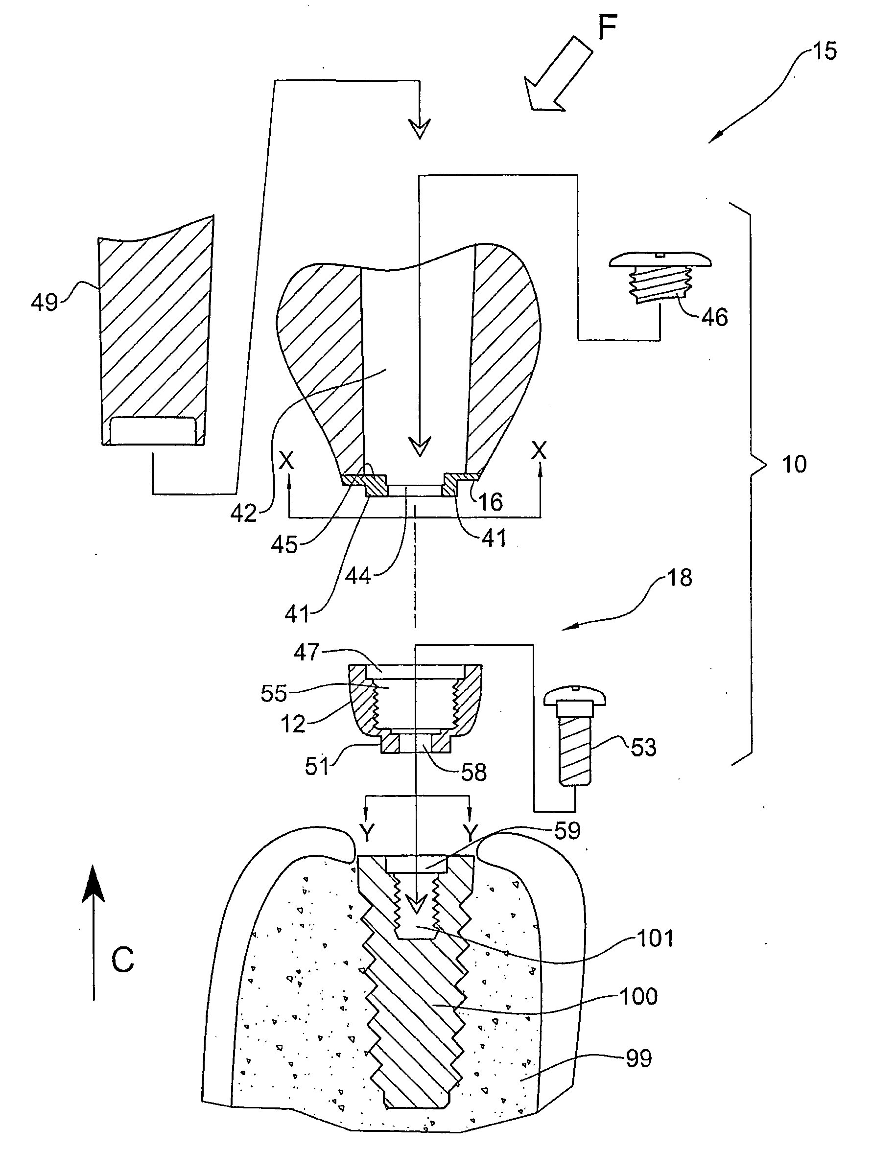
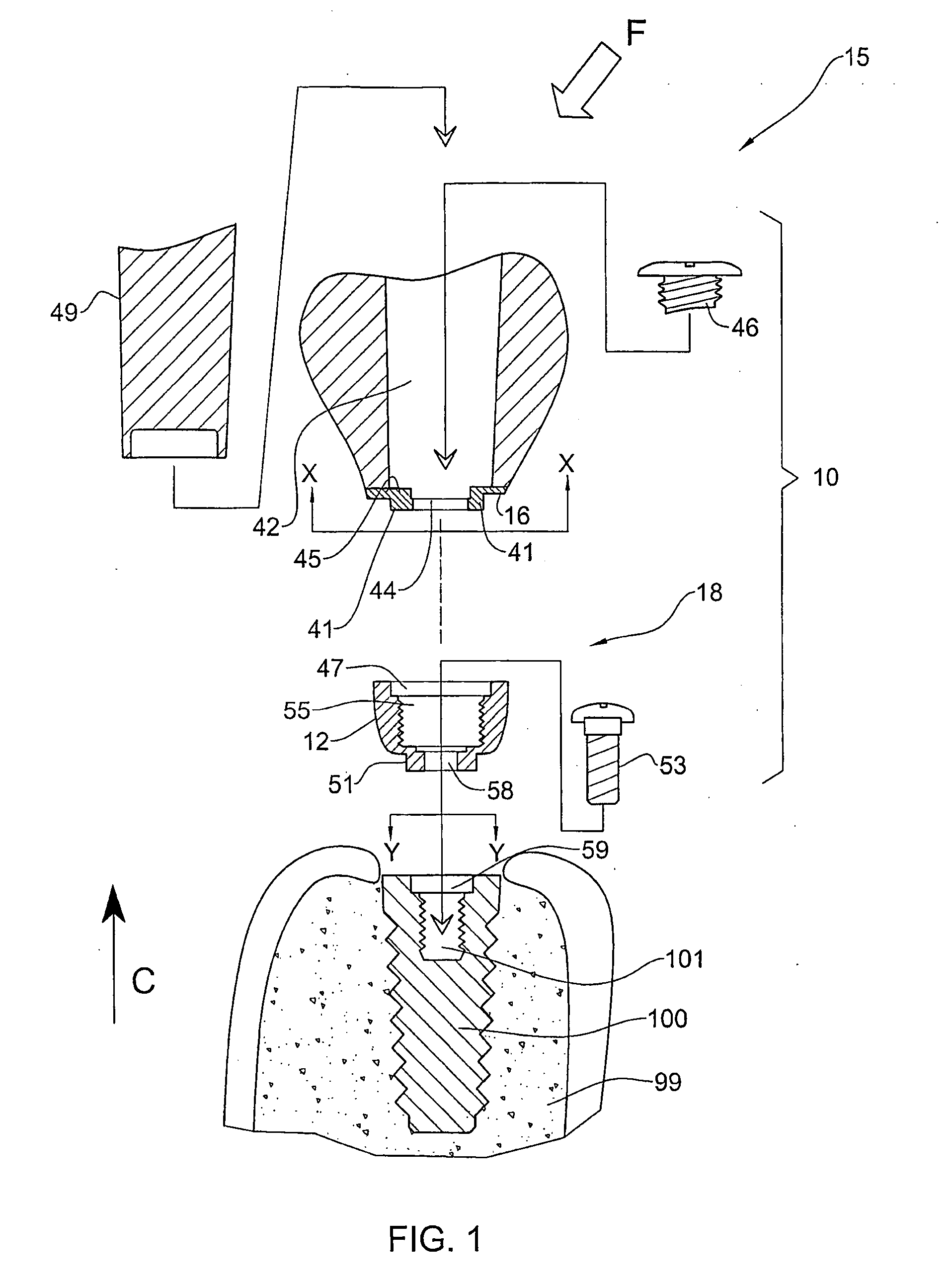
[0050] A temporary prosthesis according to the present invention, illustrated in FIG. 1 and generally designated with the numeral 10, comprises a prosthesis body 15, and an interface structure 18 for connection to the dental implant 100 that, in typical use, is already surgically implanted in the bony tissues 99 of the patient. The prosthesis body 15 is capable of absorbing loads by deforming and / or deflecting, and in this embodiment is made from a resilient, non-rigid, flexible material, preferably having an external shape, size, color and shading such that it resembles the tooth that the permanent prosthesis is to eventually replace. Suitable examples of such materials may include rubber, silicone, nylon, polyethylene, copolymers, compomers, elastomers, plastic, Teflon, and other biocompatible materials. The prosthesis body 15 may comprise a single homogenous material, or alternatively comprise different materials suitably missed or arranged therein, comprising for example differe...

second embodiment

[0070] Yet another variation of the second embodiment, illustrated in FIG. 16, is similar to that illustrated in FIG. 15, mutatis mutandis, with the following major differences. The prosthesis body 165 comprises an integral base 166, made preferably from a rigid or semi rigid material, and the bolt 167 secured the prosthesis body 165 by abutment of the head 169 and / or washer 164 against an exposed flange 168 comprised in the base 166. The bolt 167 is inserted in position via the bore 162, which can be plugged with elongate plug 161. In this configuration, practically the full prosthesis body 165, from the head 135 to the base 126, may sway or deform with respect to the implant 100, to absorb loads.

[0071] A variation of the second embodiment is illustrated in FIG. 17, which is similar to the variation of the first embodiment illustrated in FIG. 12, comprises a base 116 and a pin 111 similar to pin 11′ thereof, enabling the prosthesis 110 to be connected to an implant having the corre...


PUM


Abstract

A temporary prosthesis for use during the osseointegration process of an installed dental implant comprises load-absorbing properties and is mountable to the implant, providing an aesthetic appearance to the implant site, while preventing or minimizing loads on the implant itself.

Description

FIELD OF THE INVENTION [0001] This invention relates to dentistry, in particular to the field of prosthodontics. BACKGROUND OF THE INVENTION [0002] Dental restoration processes, including replacing the missing tooth or teeth with permanent prostheses mounted on implants embedded in bony tissues of the upper and / or lower jaws, are well known. Fixed prostheses are fixed to the implant in a nominally permanent manner, and are not designed to be removed in the normal use thereof. These are to be contrasted with mobile or implant-supported prostheses, which are removable during normal use thereof and may or may not have an implant structure in the mouth. Both fixed and mobile permanent prostheses provide the appearance of teeth, and mimic the function thereof, allowing food to be masticated etc. [0003] A number of different general procedures are known for implanting such fixed prostheses, and all start with embedding at least one implant, typically made from titanium or other medically ...

Claims


Application Information

Patent Timeline
Patent Type & Authority Applications(United States)
IPC IPC(8): A61C8/00A61C13/28
CPCA61C8/0012A61C13/0001A61C8/0048
Inventor LAST-POLLAK, MORDEHAI
Owner L P M DENTAL DEV
Why Eureka
Try Eureka