Display Panel Manufacturing Apparatus and Display Panel Manufacturing Method
a technology for display panels and manufacturing apparatuses, which is applied in the manufacture of electrode systems, instruments, electric discharge tubes/lamps, etc., can solve the problems of low production efficiency, inability to ensure high productivity, and limited increase in the adhesion speed of optical films, so as to achieve stable fixation of substrates
- Summary
- Abstract
- Description
- Claims
- Application Information
AI Technical Summary
Benefits of technology
Problems solved by technology
Method used
Image
Examples
first embodiment
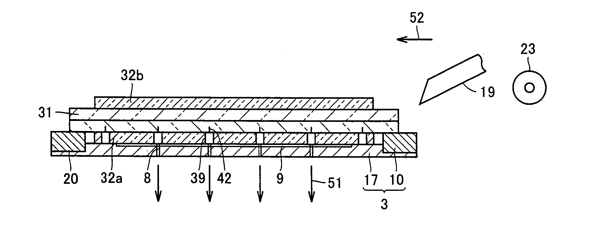
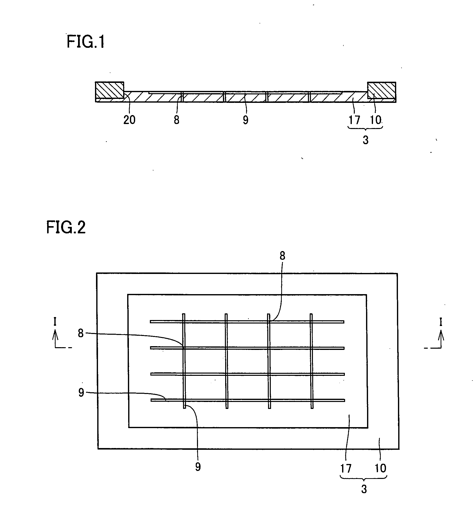
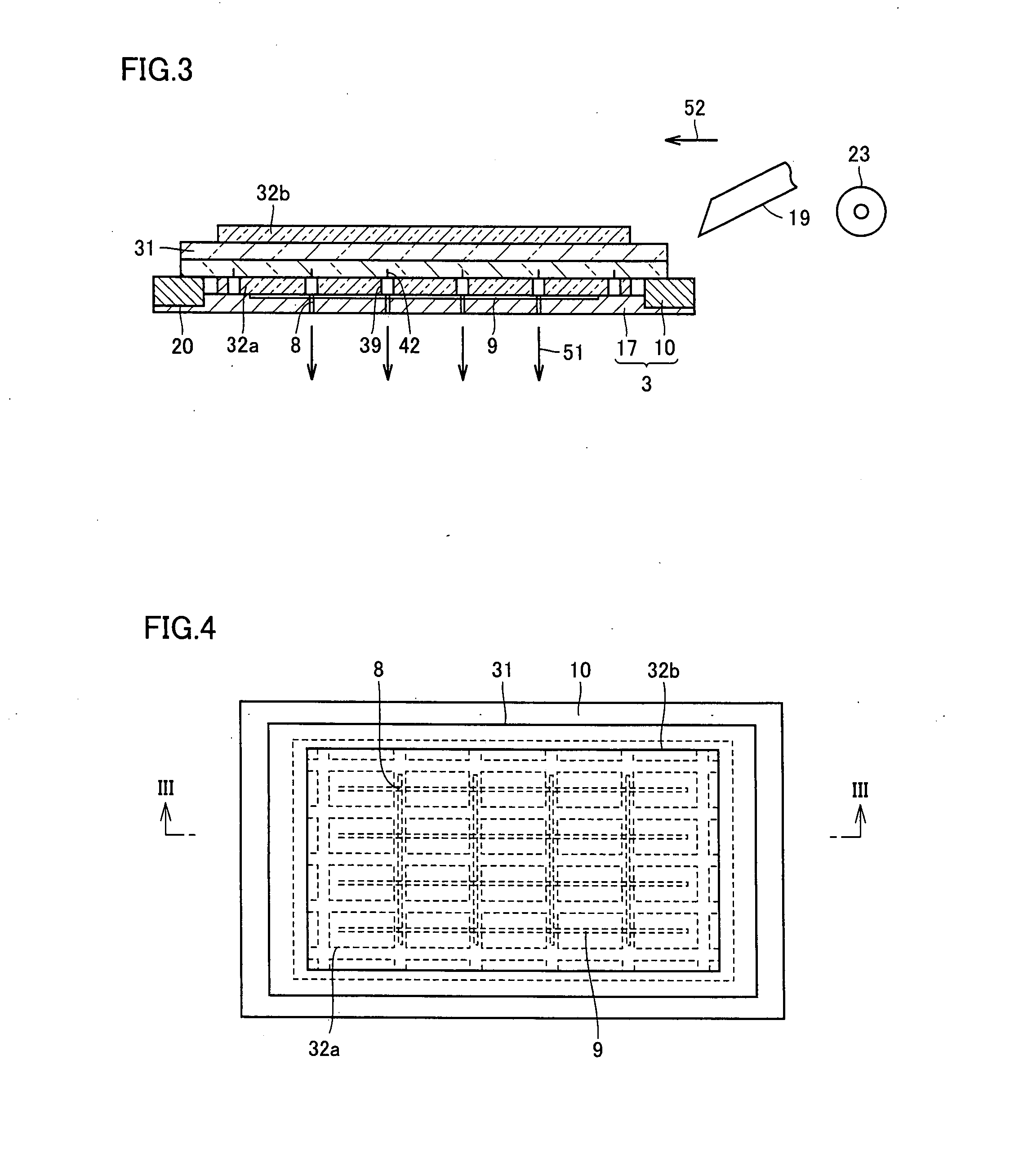
[0050] Referring to FIGS. 1 to 8 and 18 to 20, an apparatus and a method of manufacturing a liquid crystal display panel which is an example of a display panel will now be described as a first embodiment of the invention.
[0051] An apparatus of manufacturing a liquid crystal display panel of the embodiment is a dividing device which operates as follows in a step of dividing a laminated substrate into individual liquid crystal display panels. Thus, the apparatus operates to cut and remove partially an optical film arranged on a substrate surface, then forms cracks for division at a film-removed portion and divides the substrate into individual liquid crystal display cells.
[0052] As shown in FIGS. 18 and 19, the laminated substrate includes two glass substrates opposed and adhered to each other. A plurality of liquid crystal display cells are formed between the two glass substrates. Each of the liquid crystal display cells has a substantially rectangular form in a plan view, and is a...
second embodiment
[0076] Referring to FIGS. 9 to 11, description will now be given on an apparatus and a method of manufacturing a liquid crystal display panel according to a second embodiment of the invention. The apparatus of manufacturing the liquid crystal display panel according to the embodiment is a dividing device, by which an optical film arranged on a surface of a laminated substrate is partially cut and removed, then cracks for division are formed at a film-removed portion and division into individual liquid crystal display cells is performed. A stage is provided with a suction hole and a suction groove, and the suction hole is connected to an evacuation device. These structures are the same as those in the first embodiment.
[0077]FIG. 9 is a schematic cross section showing, on an enlarged scale, an outer peripheral portion of the stage on which the substrate is arranged but is not yet fixed by suction. FIG. 10 is a cross section taken along line X-X in FIG. 9. A stage 4 in this embodiment...
third embodiment
[0091] Referring to FIGS. 12 to 14, description will now be given on an apparatus and a method of manufacturing a liquid crystal display panel according to a third embodiment of the invention. The apparatus of manufacturing the liquid crystal display panel according to the embodiment is a dividing device, by which an optical film arranged on a surface of a laminated substrate is partially cut and removed, then cracks for division are formed and division into individual liquid crystal display cells is performed. A stage is provided with a suction hole and a suction groove, and the suction hole is connected to an evacuation device. These structures are the same as those in the first embodiment.
[0092]FIG. 12 is a schematic cross section of an outer peripheral portion of the stage on which the laminated substrate is arranged but is not yet fixed by suction. FIG. 13 is a cross section taken along line XIII-XIII in FIG. 12. A stage 5 in this embodiment includes plate member 17 and an int...
PUM
 Abstract
Description
Claims
Application Information
 - R&D
- Intellectual Property
- Life Sciences
- Materials
- Tech Scout
- Unparalleled Data Quality
- Higher Quality Content
- 60% Fewer Hallucinations
Browse by: Latest US Patents, China's latest patents, Technical Efficacy Thesaurus, Application Domain, Technology Topic, Popular Technical Reports.
© 2025 PatSnap. All rights reserved.Legal|Privacy policy|Modern Slavery Act Transparency Statement|Sitemap|About US| Contact US: help@patsnap.com


