Internal tourniquet for surgery

a technology of internal tourniquets and tourniquets, which is applied in the field of internal tourniquets, can solve the problems of limiting or completely preventing the use of external tourniquet systems for establishing hemostasis, and increasing the risk of injury to these non-surgical regions

a technology of internal tourniquets and tourniquets, which is applied in the field of internal tourniquets, can solve the problems of limiting or completely preventing the use of external tourniquet systems for establishing hemostasis, and increasing the risk of injury to these non-surgical regions

US20070260148A1Active Publication Date: 2007-11-08WESTERN CLINICAL ENG

Image

  • Internal tourniquet for surgery
  • Internal tourniquet for surgery

Examples


Embodiment Construction

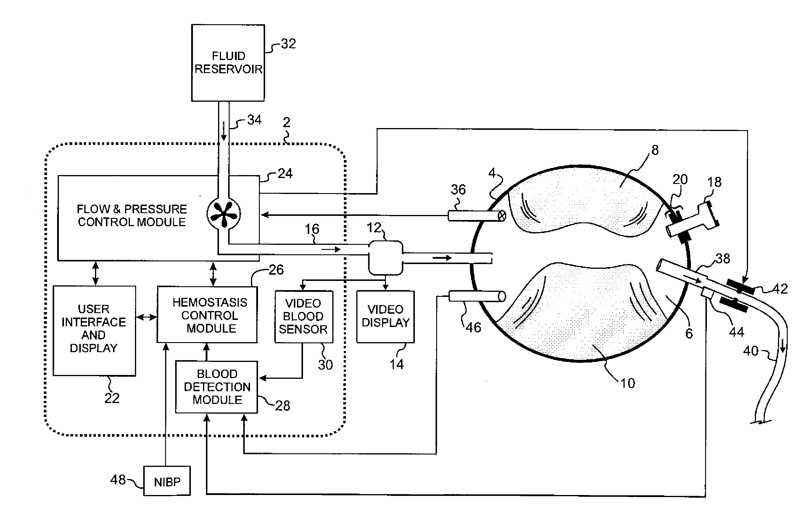
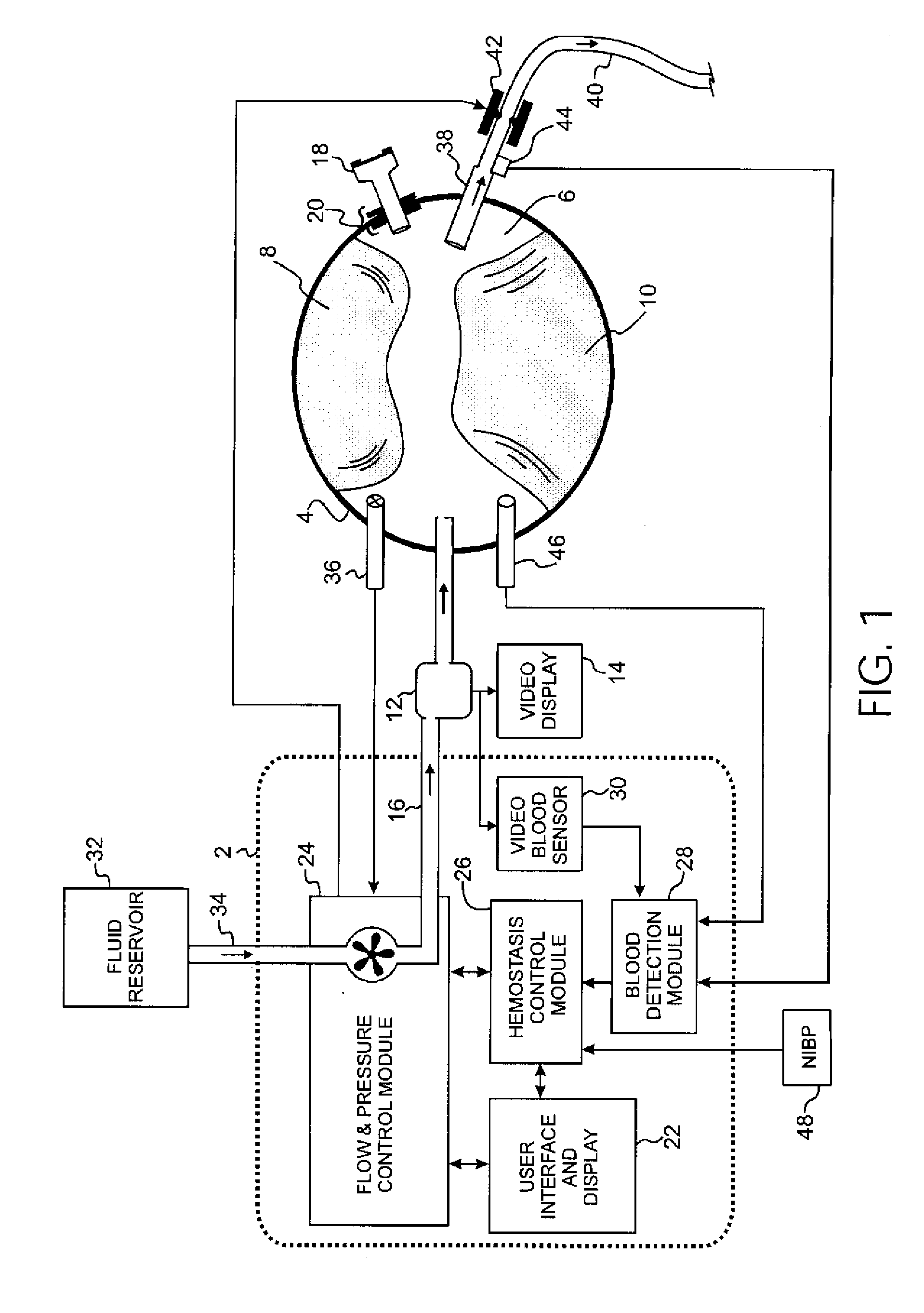
[0006] A block diagram of a preferred embodiment of the invention in use during an orthopedic surgical procedure is depicted in FIG. 1. Internal tourniquet 2 supplies clear pressurized fluid to joint capsule 4 to permit a surgical procedure to be performed within the region 6 enclosed by the joint capsule 4. Joint capsule 4 is a substantially fluid-tight sac-like envelope that encloses the cavity of a synovial joint by attaching to the circumference of the articular end of each involved bone 8 and 10.

[0007] To visualize the bones and tissues within the joint the operating surgeon inserts a scope 12 into the joint capsule 4. Scope 12 includes a cannulated sheath that provides a fluid passageway from internal tourniquet 2 to the interior region 6 of joint capsule 4, as shown in FIG. 1. Scope 12 is typical of commonly used scopes and contains fiber optic fibers coupled to a light source for transmitting light into joint capsule 4 and magnifying lenses coupled to a color video camera f...


PUM


Abstract

An internal tourniquet for establishing hemostasis within a portion of a limb to facilitate surgery controls flow of a fluid into a capsule surrounding substantially all of a human joint. Blood concentration in the capsule is sensed; and pressure in the capsule is controlled to maintain a fluid pressure in the capsule within a predetermined pressure tolerance window. The concentration of blood in the capsule is maintained below a predetermined maximum concentration while the fluid pressure is within the pressure tolerance window.

Description

FIELD OF THE INVENTION [0001] This invention pertains to tourniquets used for stopping blood flow in a portion of a surgical patient's limb to facilitate the performance of a surgical procedure. BACKGROUND OF THE INVENTION [0002] External tourniquet systems have long been used to establish hemostasis in the upper and lower limb in order to facilitate orthopedic surgical procedures. External tourniquet systems of the prior art typically include a pneumatic tourniquet cuff applied around a patient's limb proximal to a desired surgical field, and an external tourniquet instrument for supplying the cuff with gas at a pressure above the minimum pressure needed to stop arterial bloodflow past the cuff and into the surgical field for the duration of a surgical procedure. In this way, an external tourniquet system establishes a bloodless and clear surgical field in the limb distal to the cuff, allowing complex orthopedic surgical procedures to be performed with improved accuracy, safety and...

Claims


Application Information

Patent Timeline
08 Nov 2007
Publication
US20070260148A1
IPC
A61B5/02
CPC
A61B2019/464; A61B17/1355; A61B2090/064; A61B1/317; A61M3/0258; A61M2205/3313; A61M2205/3344; A61M3/0216
Inventors
MCEWEN, JAMES A.