Method of achieving high reliability of network boot computer system

a network boot and computer system technology, applied in the field of network boot computer system high reliability, can solve the problems of both servers going down together, server that should take over the boot disk may not be able to access the boot disk, and achieve the effect of reducing the workload of the system manager

Inactive Publication Date: 2007-11-08
HITACHI LTD
View PDF12 Cites 51 Cited by
  • Summary
  • Abstract
  • Description
  • Claims
  • Application Information

AI Technical Summary

Benefits of technology

[0009]According to one embodiment of this invention, in the network boot computer system, even when a fault occurs in the network switch present in the network path or the device such as the external disk device used by the server to boot, a server accessible to the boot disk through the network is always present in the network boot computer system. Then, the server takes over the boot disk to boot, making it possible to recover the application. Processing for recovering the application is automatically executed by the management computer, and a work load on the system manager can thus be reduced.

Problems solved by technology

However, when a fault occurs in the external disk device including the boot disk or in the network switch present in the network for interconnecting the server and the disk, fault recovery by the method is impossible.
For example, in a case where the server engaged in an application and the server not engaged in an application are connected to the same network switch or external disk device, when a fault occurs in the network switch or the external disk device, neither of the servers can continue the application, causing both of the servers to go down together.
Thus, in the conventional network boot computer system, when a fault occurs in the network switch in the network or the external disk device, the server that should take over the boot disk may not be able to access the boot disk.
In this case, the server cannot take over the application to recover from the fault.

Method used


Image

  • Method of achieving high reliability of network boot computer system
  • Method of achieving high reliability of network boot computer system
  • Method of achieving high reliability of network boot computer system

Examples


first embodiment

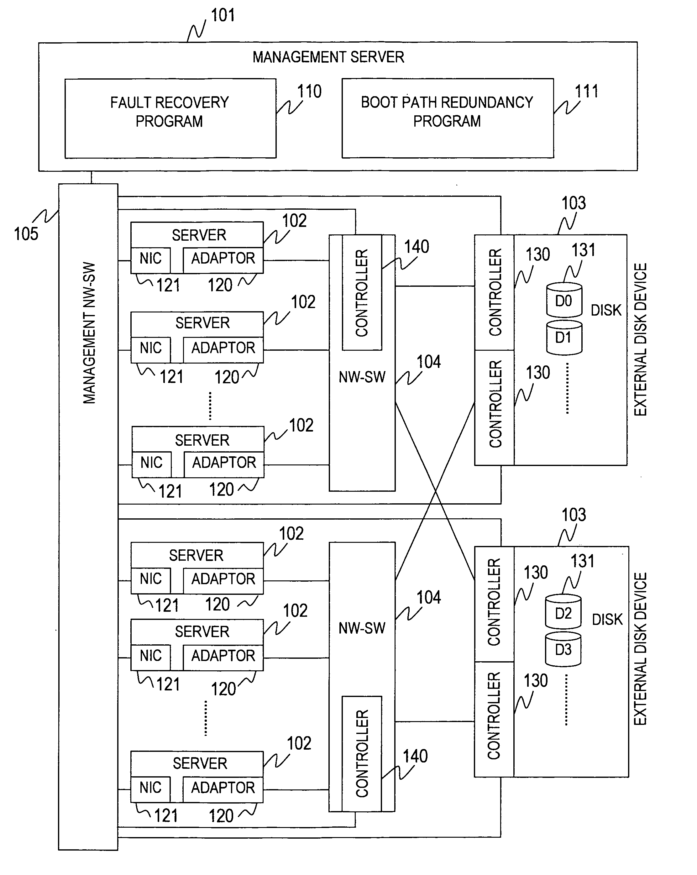
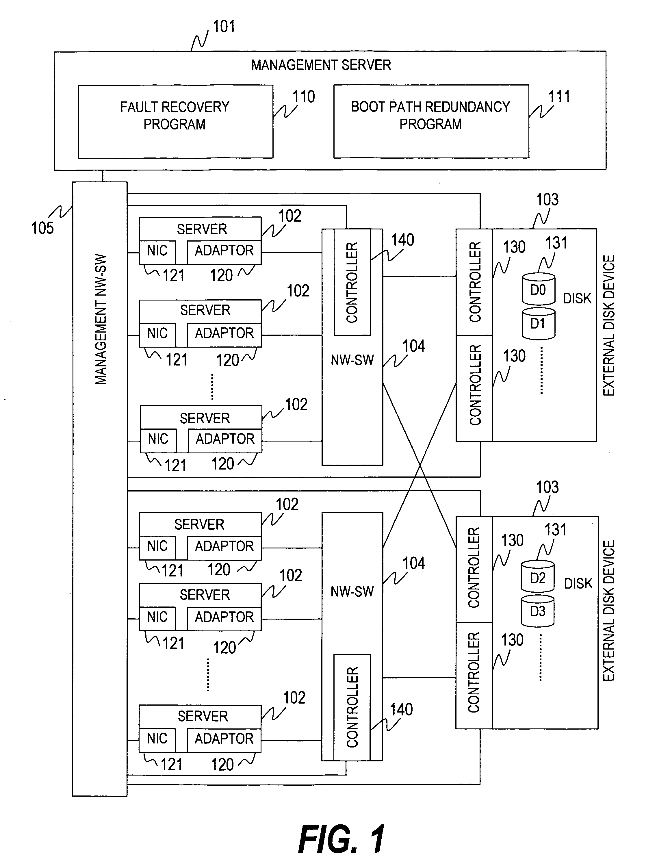
[0045]FIG. 1 is a block diagram showing a configuration of a computer system according to this invention.

[0046]The computer system of this embodiment includes a management server 101, a plurality of servers 102, a plurality of external disk devices 103, a plurality of network switches (NW-SW) 104, and a management network switch (management NW-SW) 105.

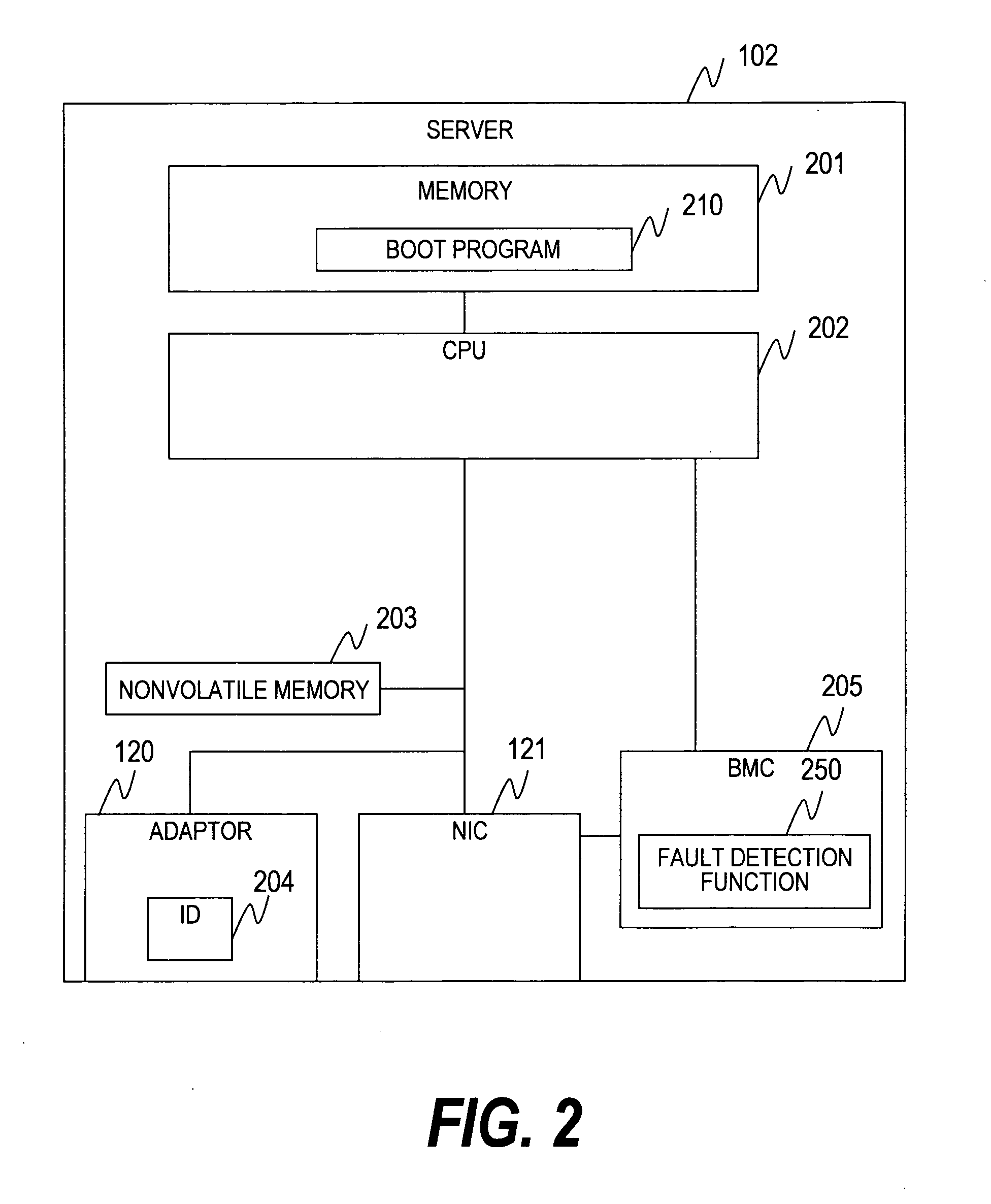
[0047]Each server 102 includes a network interface card (NIC) 121 connected to the management NW-SW 105, and a network adaptor (referred to as adaptor) 120 connected to the NW-SW 104.

[0048]The NW-SW 104 constitutes a network for interconnecting the server 102 and the external disk device 103. The NW-SW 104 may be a switch for handling Ethernet protocol, a switch of a fibre channel, or a network switch of another kind.

[0049]The management NW-SW 105 constitutes a network for interconnecting the management server 101, the server 102, the external disk device 103, and the NW-SW 104. As in the case of the NW-SW 104, the management NW-SW 105...

second embodiment

[0276]Next, this invention will be described.

[0277]The second embodiment of this invention is different from the first embodiment in that the disk synchronization program shown in FIG. 9 is not present. Only differences of the second embodiment from the first embodiment will be described below.

[0278]FIG. 21 is an explanatory diagram showing mirroring executed according to the second embodiment of this invention.

[0279]To be specific, FIG. 21 shows a method of synchronizing contents of disks 2130 and 2131 between two different external disk devices 2120 and 2121, and storing the same disk image D0.

[0280]A sever 102 of this embodiment includes a mirroring program 2100.

[0281]When a CPU 2110 executes a writing command 2111 to write data in a disk 2130, the mirroring program 2100 writes data in the disk 2130 and the same data in a disk 2131. Accordingly, updating of the disk 2130 by the server 102 is always applied to the disk 2131, and the disks 2130 and 2131 match each other in contents...

third embodiment

[0291]Next, this invention will be described.

[0292]The third embodiment of this invention is different from the first embodiment in that the disk synchronization program shown in FIG. 9 is not present, and from the second embodiment in that the mirroring program shown in FIG. 21 is not present.

[0293]FIG. 23 is an explanatory diagram showing synchronous disk creation executed according to the third embodiment of this invention.

[0294]To be specific, FIG. 23 shows a method of synchronizing contents of disks 2320 and 2321 between two different external disk devices 2310 and 2311 to store the same disk image D0 according to this embodiment.

[0295]According to this embodiment, one of serves 102 of a computer system becomes a synchronous server 2301. The synchronous server 2301 includes a synchronization program 2300. The synchronous server 2301 may be a server 102 engaged in application or not engaged in application. The synchronous server 2301 can access disks 2320 and 2321 via an adaptor...


PUM


Abstract

In a network computer system, recovery may be impossible from a fault when the fault occurs in a network switch in a network or a device such as an external disk device. Provided is a computer system that includes a plurality of servers, a plurality of networks, a plurality of external disk devices, and a management computer, in which the management computer detects a fault which is occurred, retrieves an application stop server inaccessible to the used disk due to the fault, retrieves the disk for storing the same contents as contents stored in the disk used by the retrieved application stop server and the external disk device including the disk, retrieves an application resuming server capable of accessing the retrieved external disk device, and transmits an instruction to boot by using the retrieved disk to the retrieved application resuming server.

Description

CLAIM OF PRIORITY[0001]The present application claims priority from Japanese patent application P2006-117822 filed on Apr. 21, 2006, the content of which is hereby incorporated by reference into this application.BACKGROUND OF THE INVENTION[0002]This invention relates to a method of recovering an application when a fault occurs in a device included in a network boot server computer system.[0003]There is made available a network boot computer system in which each server boots by reading a program of an operating system (OS) or the like from a disk of an external disk device in an environment having a plurality of servers connected to the external disk device via a network. In the network boot computer system, the plurality of servers are connected to the external disk device via the network and a network switch. Thus, a boot disk referred to by a certain server can be referred to by another server.[0004]Regarding the network boot computer system, a fault recovery method of taking over...

Claims


Application Information

Patent Timeline
Patent Type & Authority Applications(United States)
IPC IPC(8): G06F11/00
CPCG06F9/4406G06F11/2046G06F11/2028G06F11/0793
Inventor HATASAKI, KEISUKENAKAJIMA, TAKAO
Owner HITACHI LTD
Why Eureka
Try Eureka