Suction device for pick power tool

Active Publication Date: 2007-11-15
HILTI AG
View PDF5 Cites 19 Cited by
  • Summary
  • Abstract
  • Description
  • Claims
  • Application Information

AI Technical Summary

Benefits of technology

[0021] Advantageously, the main curvature axis, which is mathematically expressed by zero, extends parallel to an orientation of the connection device, which additionally reduces the number of points of undesirable turbulence in the interior of the suction device.
[0022] Advantageously, the suction device has at least one suction opening. The suction opening is provided between the first baffle wall and the first end of the suction device. Through this opening, environmental air for rinsing the region between the first baffle wall and the fi

Problems solved by technology

In particular, dust particles cause contamination of the environment, e.g., interior spaces of a building, and adversely affect operation of the power tool.
The drawback of the known solution consist in that many dust particles of different sizes can reach the tool holder of the power tool and cause an increased wear of the tool holder.
Because of entrainment of the dust in the tool holder, an increase wear of the working tool shank

Method used


Image

  • Suction device for pick power tool
  • Suction device for pick power tool
  • Suction device for pick power tool

Examples


Example

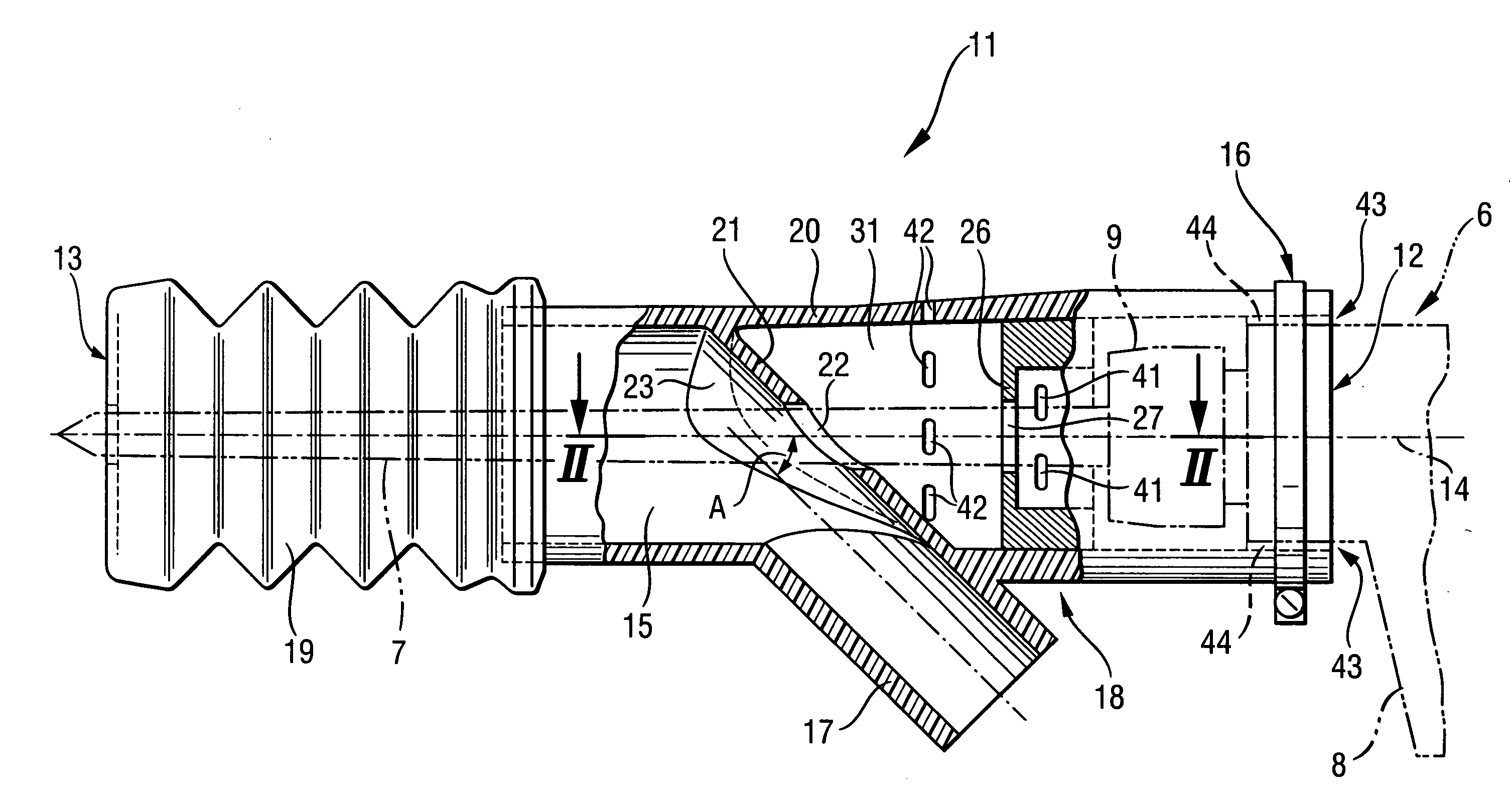
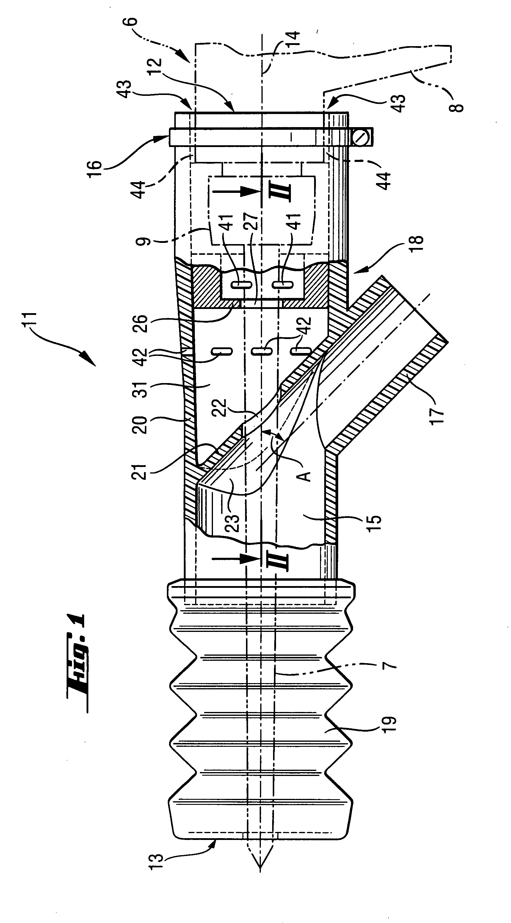
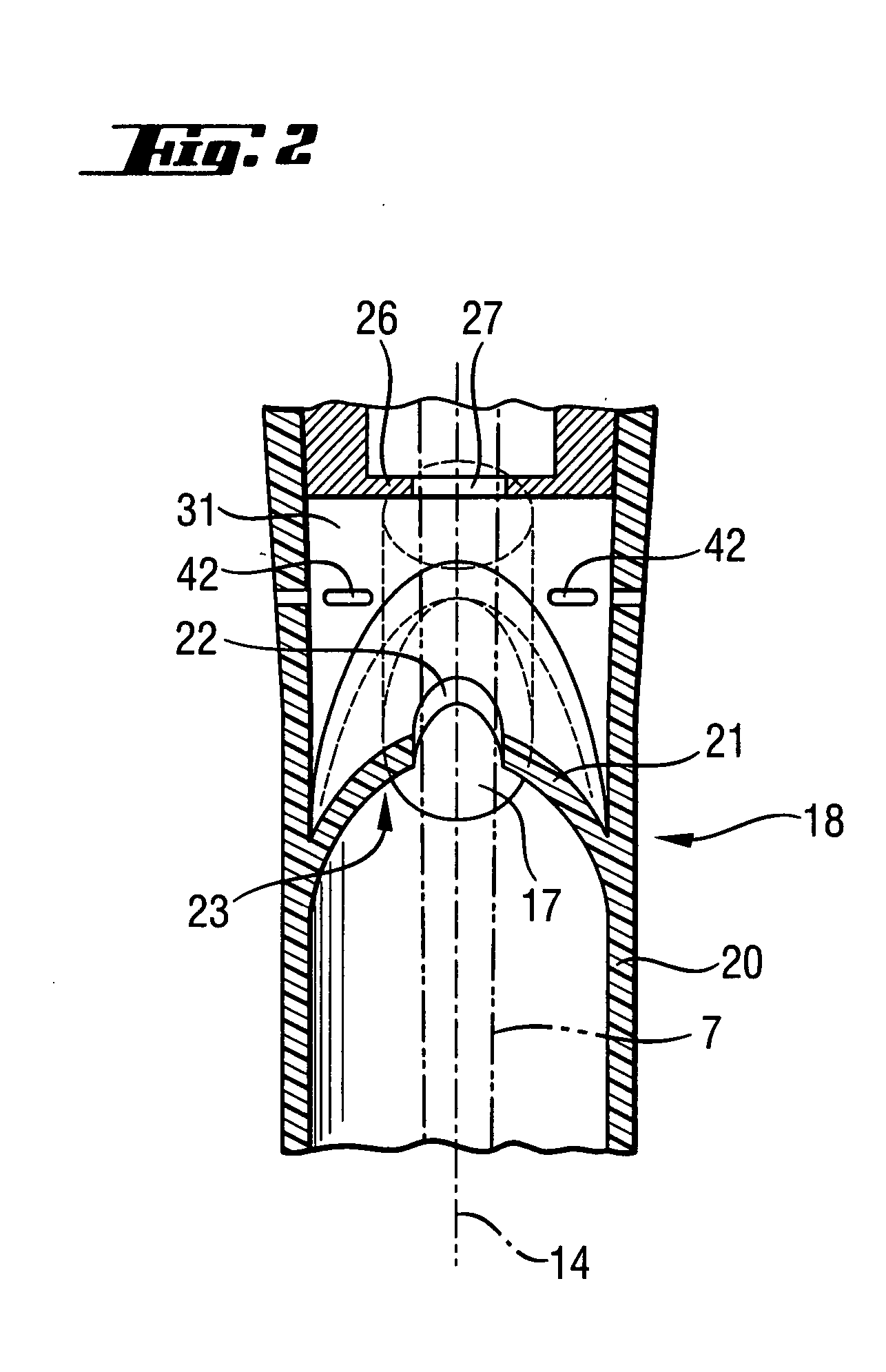
[0030] A suction device 11 according to the present invention for a pick power tool 6 such as a hammer drill and which is shown in FIGS. 1-2, has a first end 12 and an opposite second end 13. The suction device 11 extends along a longitudinal axis 14 and has a receiving chamber 15 that regionwise surrounds a working tool 7 of the pick power tool 6. The receiving chamber 15 is formed by a rigid, tubular section 18 and an elastic section 19. The rigid section 18 extends from the first end 12 of the suction device 12 in a direction of the second end 13 of the suction device 11. The elastic section 19 adjoins the rigid section 18 in the direction of the second end 13 and extends up to the second end 13, with a free end of the elastic section 19 forming the second end 13 of the suction device 11.

[0031] On the first end 12 of the suction device 11, there is provided a securing device 16 for securing the suction device 11 on the pick power tool 6. The securing device 16 is formed, in the ...


PUM


Abstract

A suction device for a pick power tool includes a securing device provided at the first axial end of the suction device for securing the suction device (11) on the pick power tool (6), a connection element(17) for a vacuum source inclined to the longitudinal axis (14) of the suction device (11), and a first baffle wall (21) and at least one further baffle wall (26) spaced from the first baffle wall (21), with the first baffle wall being located between the connection element (17) and the first end (12) of the suction device (11) and the at least one further baffle wall (21) being located between the first baffle wall and the first end (12), and the first baffle wall (21) and the second baffle wall (26) each having, respectively, a through-opening (22, 27) for the working tool (7) of the pick power tool (6).

Description

BACKGROUND OF THE INVENTION [0001] 1. Field of the Invention [0002] The present invention relates to a suction device for a pick power tool and which extends along a longitudinal axis and having opposite first and second ends, with the suction device including a receiving chamber for regionwise surrounding of a working tool of the pick power tool, a securing device provided at the first end of the suction device for securing the suction device on the pick power tool, and a connection element for a vacuum source extending at an angle to the longitudinal axis of the suction device. [0003] 2. Description of the Prior Art [0004] When treating a mineral constructional component, e.g., a concrete wall or a concrete ceiling with a working tool of a pick power tool such as hammer drill, combi- or chisel hammer, pieces of the removable material and dust are produced. In particular, dust particles cause contamination of the environment, e.g., interior spaces of a building, and adversely affec...

Claims


Application Information

Patent Timeline
IPC IPC(8): A47L9/00
CPCB23Q11/0046B08B15/04
Inventor BLEICHER, JOCHENOHLENDORF, OLIVERHOLZMEIER, GEORG
Owner HILTI AG
Why Eureka
Try Eureka