

Liquid-jet head and liquid-jet apparatus
a liquid-jet recording and liquid-jet technology, which is applied in the direction of metal-working equipment, printing, writing implements, etc., can solve the problems of negative influence of ink ejection, large size of ink-jet recording head in longitudinal direction of pressure-generating chamber, and inability to achieve the effect of reducing size and improving liquid-jet properties
- Summary
- Abstract
- Description
- Claims
- Application Information
AI Technical Summary
Benefits of technology
Problems solved by technology
Method used
Image

Examples
embodiment 1
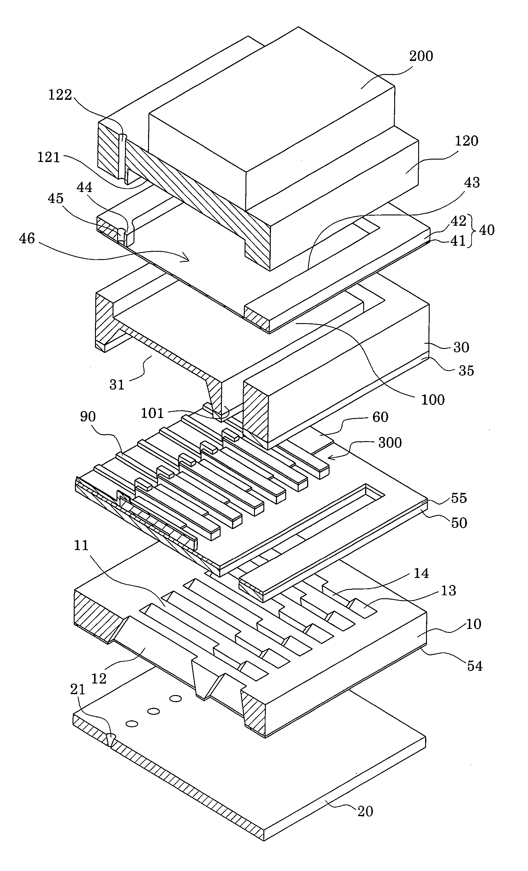
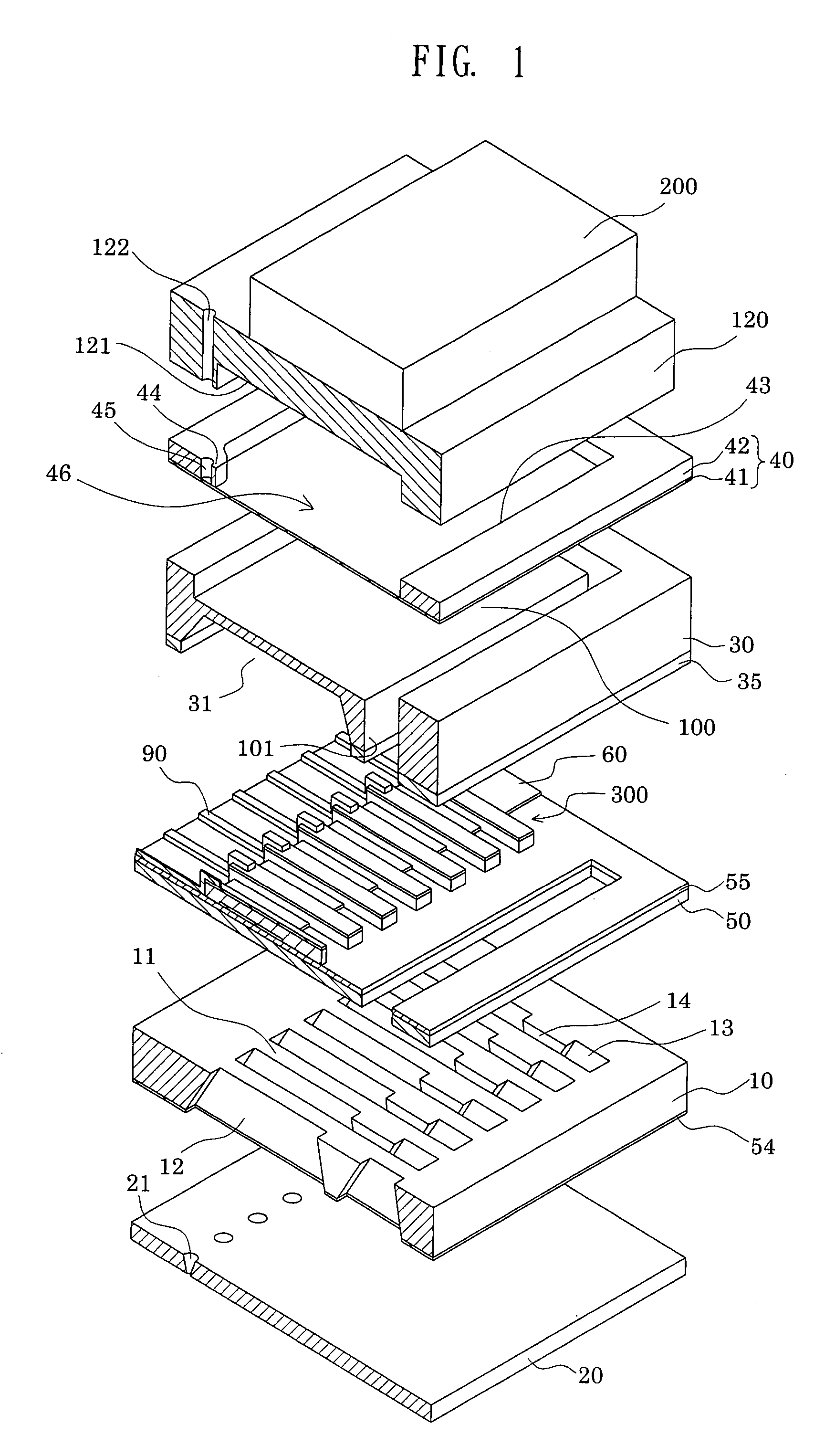
[0044]FIG. 1 is an exploded perspective view showing an ink-jet recording head that is an example of a liquid-jet head according to Embodiment 1 of the invention. FIG. 2A is a plan view of FIG. 1. FIG. 2B is a cross-sectional view taken along the line A-A′ of FIG. 2A. As illustrated, a passage-forming substrate 10 is formed of a single-crystal silicon substrate with (110) crystal plane orientation in this embodiment. In addition, an elastic film 50, made of silicon dioxide, and having a thickness of 0.5 μm to 2 μm, is previously formed on one surface of the passage-forming substrate 10 by thermal oxidization in this embodiment.
[0045] In the passage-forming substrate 10, pressure-generating chambers 12 are provided by anisotropically etching the passage-forming substrate 10 from the other surface thereof. The pressure-generating chambers 12 are partitioned by a plurality of compartment walls 11, and are arranged in the width direction thereof (the shorter-side direction). Moreover, ...
embodiment 2
[0076]FIG. 6A is a plane view of an ink-jet recording head according to Embodiment 2, and FIG. 6B is a cross-sectional view taking along the line B-B of FIG. 6A. It should be noted that the same reference numerals are assigned to the same components as those of Embodiment 1, and the redundant descriptions of those are omitted here.
[0077] As shown in FIG. 6B, a compliance plate 40A is constituted of a sealing film 41, and a fixing plate 42A. The fixing plate 42A is provided with an opening portion 43B which opens to a part facing the through hole 101 in a region, facing the reservoir 100, of the compliance plate 40. The fixing plate 42A is also provided with an opening portion 43A which opens to a part surrounding the protrusion 44 where the introducing path is provided in the region facing the reservoir 100. The fixing plate 42A further includes a beam portion 47 which separates these opening portions 43A and 43B from each other. Specifically, a flexible portion having flexibility ...
embodiment 3
[0079]FIG. 7 is a cross-sectional view of an ink-jet recording head according to Embodiment 3 of the invention. It should be noted that the same reference numerals are assigned to the same components as those of Embodiment 1, and the redundant descriptions of those are omitted here.
[0080] As shown in FIG. 7, in Embodiment 3, the drive circuit 200A configured of a drive IC is not mounted on the head case 120, but on the top of the passage-forming substrate 10 while being arranged in parallel with the protection plate 30. In addition, the drive circuit 200A is separated from the protection plate 30.
[0081] The drive circuit 200A can be mounted directly on the lead electrodes 90 withdrawn from the piezoelectric elements 300 by use of an anisotropic conductive adhesive agent (ACF, ACP, NCF, NCP, or the like), or by means of an ultrasonic bonding method. It should be noted that the drive circuit 200A is not limited to a drive IC, but may be a tape carrier package (TCP) or the like havin...
PUM
| Property | Measurement | Unit |
|---|---|---|
| Pressure | aaaaa | aaaaa |
| Electrical resistance | aaaaa | aaaaa |
Abstract
Description
Claims
Application Information