Liquid crystal display element

a liquid crystal display and element technology, applied in non-linear optics, instruments, optics, etc., can solve the problems of deteriorating display quality, affecting the and reducing the filling step, so as to ensure the display quality and reliability of the liquid crystal display element. , the effect of shortening the filling step

Active Publication Date: 2007-11-15
PANASONIC LIQUID CRYSTAL DISPLAY CO LTD +1
View PDF8 Cites 24 Cited by
  • Summary
  • Abstract
  • Description
  • Claims
  • Application Information

AI Technical Summary

Benefits of technology

[0025]According to the present invention, in filling the liquid crystal in the inside of a cell which is formed by the pair of substrates which face each other and the frame-like sealing material which is sandwiched between the peripheral ...

Problems solved by technology

However, in this case, as the sealing material, a heat-curing sealing material cannot be used and only an ultraviolet-curing sealing material can be used.
When leaking of light occurs, a display contrast is lowered on the peripheral portion of the display screen thus remarkably deteriorating a display quality.
Particularly, in displaying bright characters, figures and the like on the dark display screen, there arises a drawback that the display is largely influenced by the leaking of light.
However, when the b...

Method used


Image

  • Liquid crystal display element
  • Liquid crystal display element
  • Liquid crystal display element

Examples


embodiment 1

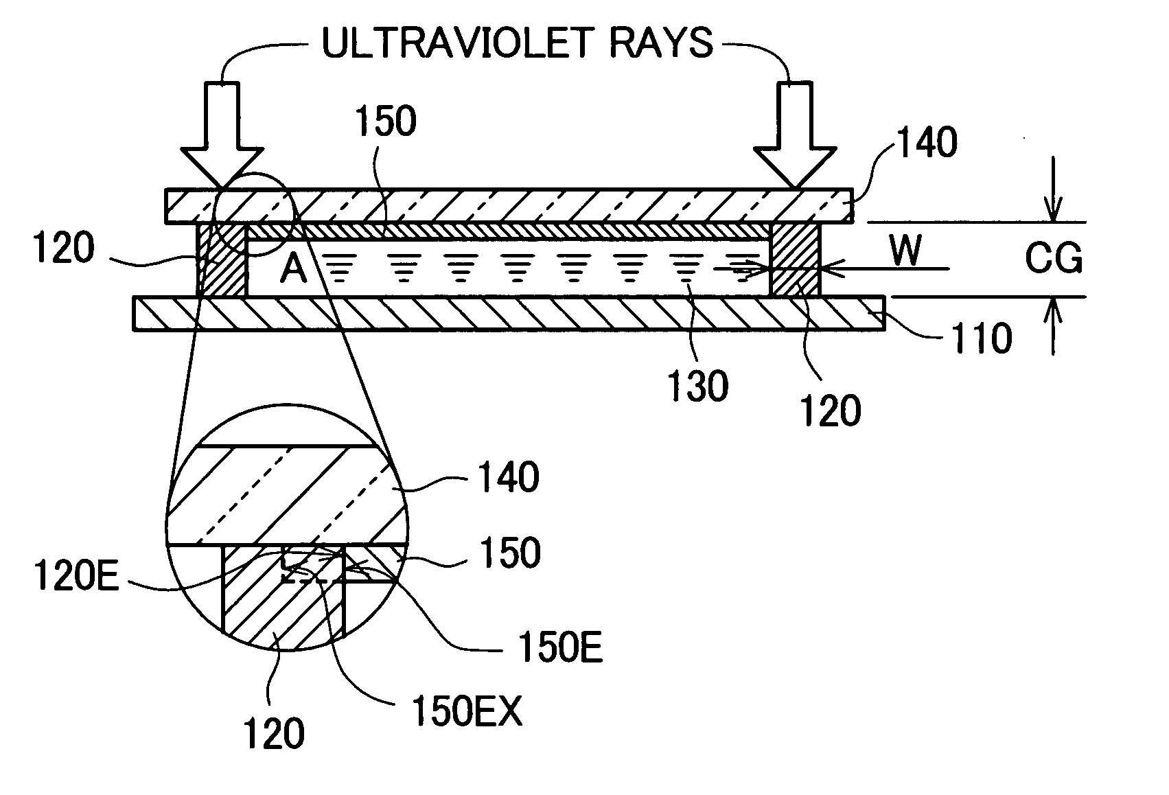
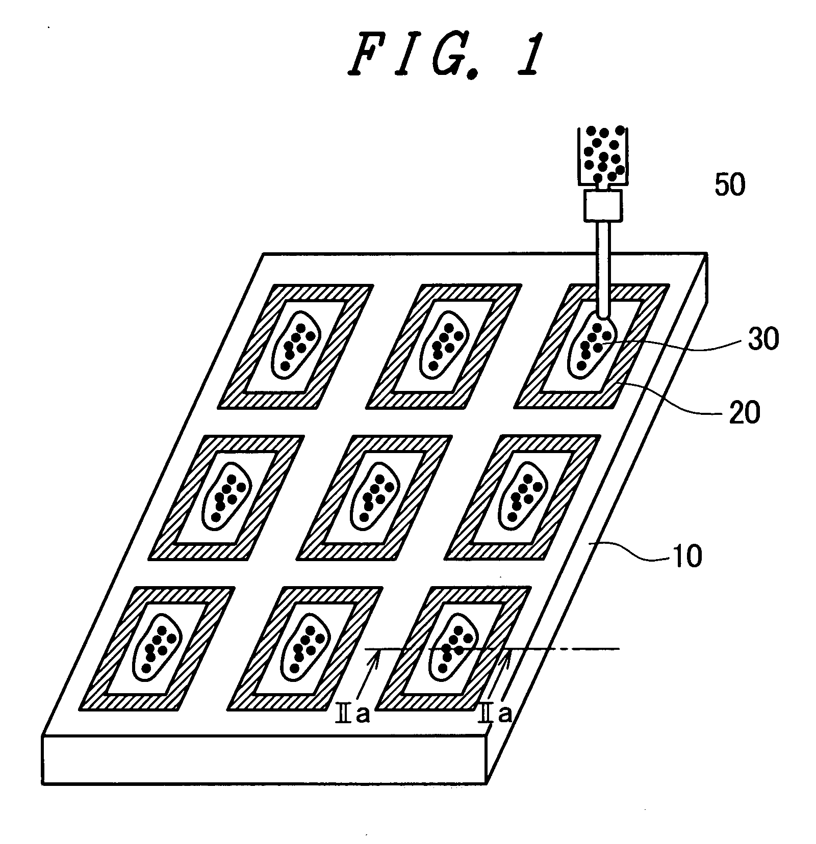
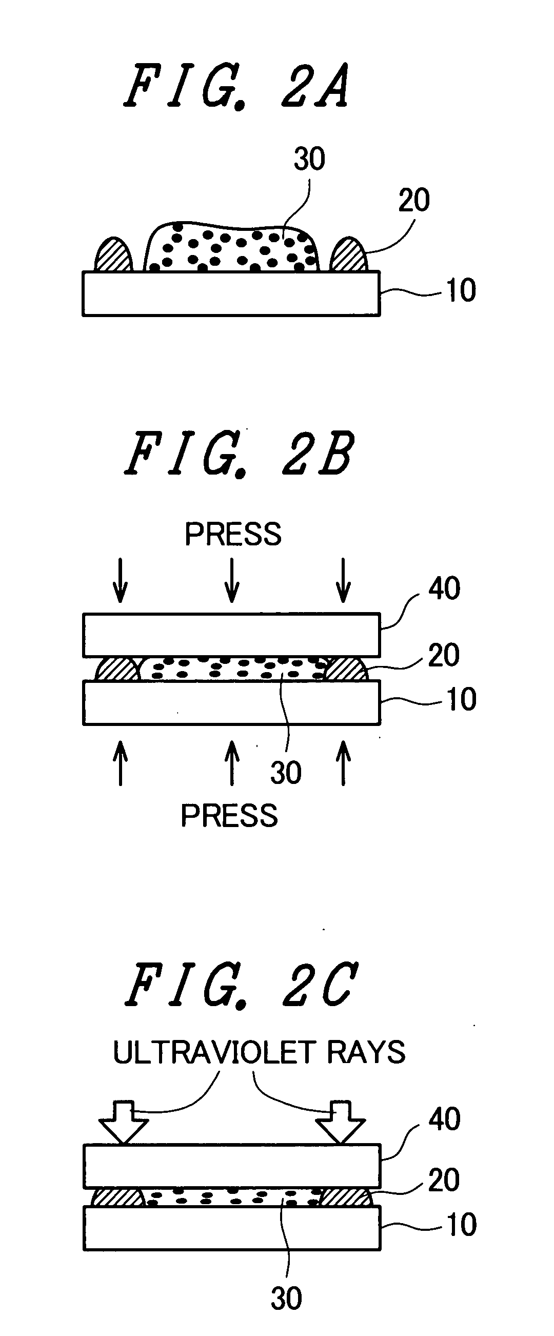
[0042]FIG. 3A is a plan view of the liquid crystal display element according to a first embodiment of the present invention, and FIG. 3B is a cross-sectional view of the liquid crystal display element shown in FIG. 3A taken along a line IIIb-IIIb. The method for sealing the liquid crystal using a dropping injection method is explained in conjunction with cross-sectional views shown in FIG. 2A and FIG. 2B which correspond to a cross-sectional view of one frame-like sealing material 20 shown in FIG. 1 taken along a line IIa-IIa. However, the cross-sectional view shown in FIG. 3B corresponds to the cross-sectional view shown in FIG. 2C.

[0043]In FIG. 3A and FIG. 3B, numeral 110 indicates a back substrate of a liquid crystal element, numeral 140 indicates a face substrate of the liquid crystal element, numeral 130 is a liquid crystal composition, numeral 120 indicates a frame-like ultraviolet curing sealing material, numeral 150 indicates a black matrix in which a large number of opening...

embodiment 2

[0051]In the above-mentioned embodiment 1, the outer periphery 150E of the black matrix 150 simply comes into contact (tangent) with an inner periphery 120E of the frame-like ultraviolet curing sealing material 120 or the overlapping width of the frame-like ultraviolet curing sealing material 120 and the black matrix 150 is set to 0.2 mm or less. In the above-mentioned embodiment 1, to impart the optical characteristic equivalent to the optical characteristic of the black matrix 150 to the ultraviolet curing sealing material 120, for example, it is necessary to sufficiently take the optical density OD into consideration. In this embodiment, the ultraviolet curing of the frame-like ultraviolet curing sealing material 120 can be sufficiently performed while positively overlapping the frame-like ultraviolet curing sealing material 120 and the peripheral portion of the black matrix 150 to each other to alleviate the conditions such as the optical density OD which the ultraviolet curing ...


PUM


Abstract

In manufacturing a liquid crystal display element which includes a black matrix, in curing an ultraviolet curing sealing material after filling liquid crystal using a dropping injection method, there has been a possibility that a radiation quantity of ultraviolet rays to the sealing material is insufficient and hence, the curing is not sufficiently performed thus largely lowering the reliability of the liquid crystal display element. According to the present invention, an overlapping width of a frame-like sealing material and a black matrix on a peripheral portion along a display region is suppressed to 0.2 mm or less, or a region of the black matrix which is overlapped to the frame-like sealing member is patterned to include a light transmitting portion.

Description

CROSS-REFERENCE TO RELATED APPLICATIONS[0001]The disclosure of Japanese Patent Application No. 2006-131569 filed on May 10, 2006 including the specification, drawings and abstract is incorporated herein by reference in its entirety.BACKGROUND[0002]1. Field of the Invention[0003]The present invention relates to a liquid crystal display element in which a pair of substrates is arranged to face each other and is fixed to each other by way of a frame-like sealing member with a predetermined gap therebetween and liquid crystal is sealed between both substrates inside the frame-like sealing member, and more particularly to a liquid crystal display element including a black matrix which surrounds a group consisting of a large number of display pixels which are formed inside the frame-like sealing member and provides along the frame-like sealing member.[0004]2. Description of the Related Arts[0005]In the active-matrix-type liquid crystal display element which constitutes one type of the liq...

Claims


Application Information

Patent Timeline
IPC IPC(8): G02F1/1339
CPCG02F1/1339G02F1/133512
Inventor KOBAYASHI, SETSUOMIWA, HIROAKIISHII, KATSUHIKOYAMAMOTO, TAKASHI
Owner PANASONIC LIQUID CRYSTAL DISPLAY CO LTD
Why Eureka
Try Eureka