

Optical device and coating applicator
Inactive Publication Date: 2007-11-15
KURARAY CO LTD
View PDF4 Cites 10 Cited by
- Summary
- Abstract
- Description
- Claims
- Application Information
AI Technical Summary
Benefits of technology
[0022] In the optical device of the present invention, the thickness of the friction-reducing agent on the surface of the optical sheet is very small, i.e., 0.3 nm or more and 10 nm or less, and therefore the friction-reducing agent is less likely to be accumulated in valley portions of unit lenses, prisms or randomly uneven surface of the optical sheet. Hence, a projected light beam is prevented from being refracted and reflected in directions not originally intended, whereby stray light is less likely to be generated. Therefore, in a rear projection type display device to which the transmission type screen as the optical device of the present invention is mounted, a high quality image without the stray light phenomenon can be displayed. In addition, since the friction-reducing agent is less likely to be accumulated in valley portio
Problems solved by technology
Sho 60-61738 is applied to the Fresnel lens sheet 1, a problem arises in that a region around the optical center thereof is remarkably bright when the transmission type screen 3 is viewed obliquely from above or below.
Sho 60-61738 is applied to the lenticular lens sheet 2, a problem arises in that vertical streak-like unevenness in brightness is noticeable when the transmission type scre
Method used
View moreImage
Smart ImageViewing Examples

Examples
 PUM
 Abstract
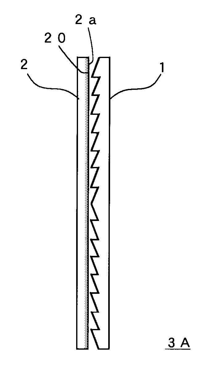
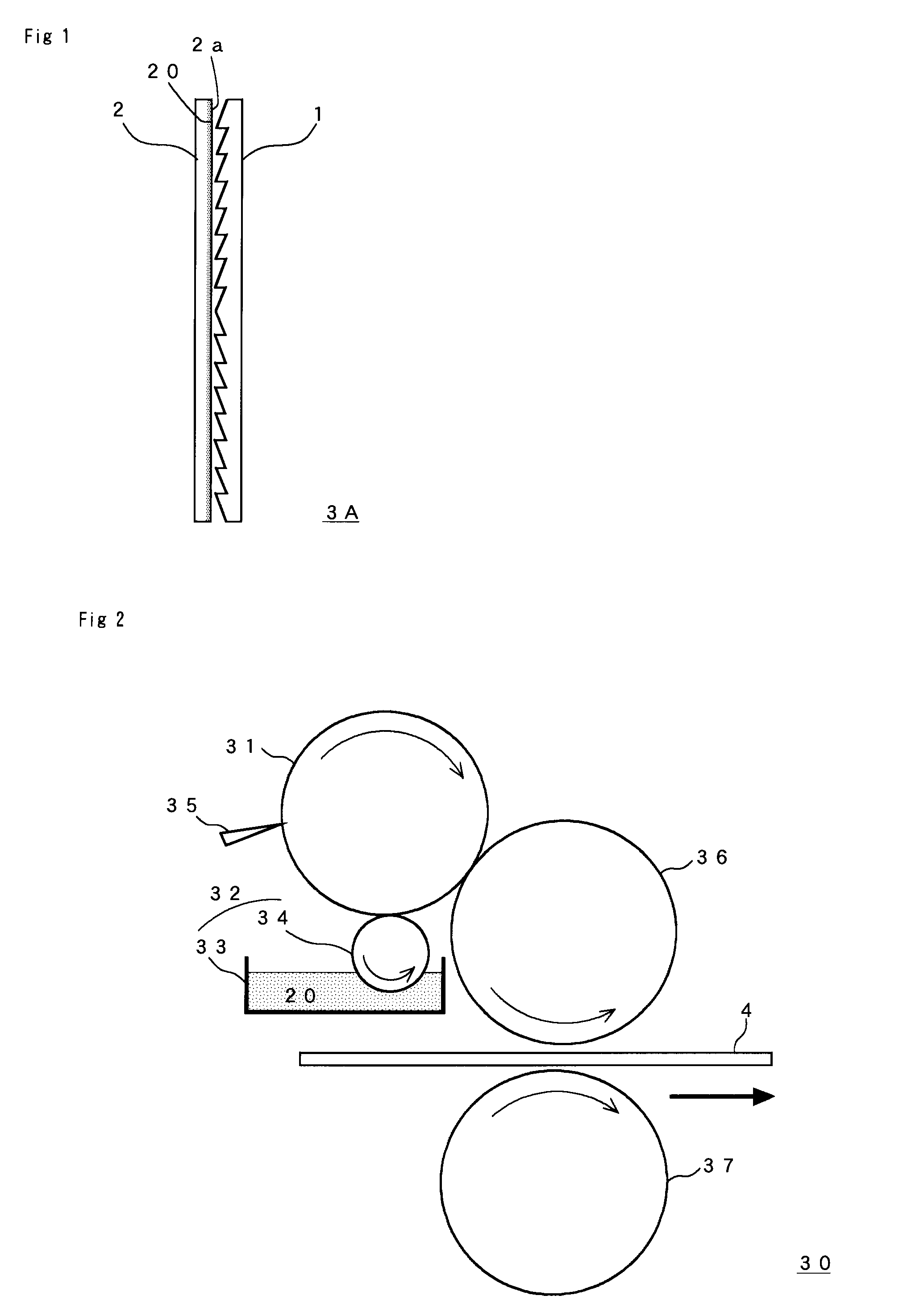
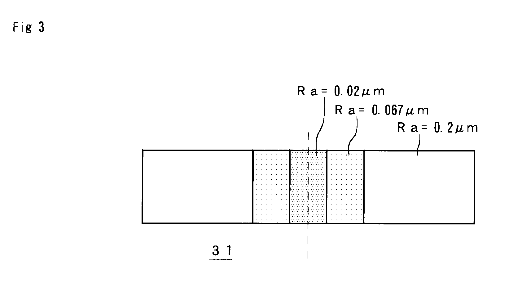
In a transmission type screen and other optical devices formed by combining optical sheets such as a Fresnel lens sheet and a lenticular lens sheet, the generation of stray light and defective appearance caused by a friction-reducing agent are prevented. In the optical devices such as a transmission type screen 3 formed by combining a plurality of optical sheets such as a Fresnel lens sheet 1 and a lenticular lens sheet 2, a friction-reducing agent 20 is provided on a surface of at least one of the optical sheets at a thickness of 0.3 nm or more to 10 nm or less. A coating applicator 30 for the friction-reducing agent 20 includes: a transfer roller 31; coating liquid-supplying means 32 for supplying the coating liquid 20 to the transfer roller 31; and scraping means 35 for adjusting the thickness of the coating liquid 20 adhering to the transfer roller 31. In the coating liquid 30, the surface roughness Ra (JIS B 0601-1982) of the transfer roller 31 is set to 0.01 to 1 μm.
Description
[0001] This application is a Continuation-in-Part of application PCT / JP2006 / 301520 filed on Jan. 31, 2006, which claims the benefits of application JP2005-024628 filed Jan. 31, 2005 and application JP2005-135338 filed May 6, 2005. The entire disclosure of each of these prior applications is hereby incorporated by reference herein in its entirety. BACKGROUND OF THE INVENTION [0002] 1. Field of the Invention [0003] The present invention relates to an optical device such as a transmission type screen for use in a rear projection type display device and the like, to a method for manufacturing the same, and to a coating applicator useful in the manufacturing method. [0004] 2. Description of the Related Art [0005] Conventionally, in a rear projection type display device, a transmission type screen 3 is used which includes a Fresnel lens sheet 1 and a lenticular lens sheet 2 intimately contacting each other, as shown in FIG. 6. [0006] Generally, the Fresnel lens sheet 1 is composed of a Fr...
Claims
Login to View More Application Information
Patent Timeline
 IPC IPC(8): G02B5/02
CPCB05C1/083G03B21/625G03B21/10G02B3/005G02B3/0068G02B3/08G02B5/0221
InventorMONOE, HIROYUKIYASUDA, KOUZOYANAGAWA, YUKIHIROKIMURA, OSAMUABE, YOSHIOSAITO, KATASHI
OwnerKURARAY CO LTD