Method for operation of a converter circuit, as well as an apparatus for carrying out the method

a converter circuit and method technology, applied in the field of power electronics, can solve the problems of permanent distortion, damage or even destruction, and achieve the effect of simple operation, low circuit complexity, and easy implementation

Active Publication Date: 2007-11-15
ABB (SCHWEIZ) AG
View PDF3 Cites 20 Cited by
  • Summary
  • Abstract
  • Description
  • Claims
  • Application Information

AI Technical Summary

Benefits of technology

[0005] A method is disclosed for operation of a converter circuit, by means of which it is possible to actively damp distortion, caused by LCL filters connected to the converter circuit, in the filter output currents and filter output voltages. An apparatus is disclosed, by means of which the method can be carried out in a particularly simple manner.
[0006] The converter circuit has a converter unit with a multiplicity of drivable power semiconductor switches, and an LCL filter which is connected to each phase connection of the converter unit. In an exemplary method for operation of the converter circuit, the drivable power semiconductor switches are now driven by means of a drive signal which is formed from reference voltages. According to the disclosure, the reference voltages are formed from the subtraction of damping voltages from reference-phase connection voltages, with the damping voltages being formed from filter capacitance currents (which are weighted with a variable damping factor) of the LCL filters. The damping voltages are thus proportional to the filter capacitance currents and are then subtracted from the reference-phase connection voltages, which is equivalent to connection of a damping resistance to each phase connection of the converter unit. Distortion, that is to say undesirable oscillations, in the filter output currents and filter output voltages can therefore advantageously be actively damped, so that this type of distortion is greatly reduced

Problems solved by technology

The converter circuit mentioned above is subject to the problem but the LCL filters can cause permanent distortion, that is to say undesirable oscillations, in the filter output currents and filter voltages, resulting from resonant oscillations of the LCL fi

Method used


Image

  • Method for operation of a converter circuit, as well as an apparatus for carrying out the method
  • Method for operation of a converter circuit, as well as an apparatus for carrying out the method
  • Method for operation of a converter circuit, as well as an apparatus for carrying out the method

Examples


Embodiment Construction

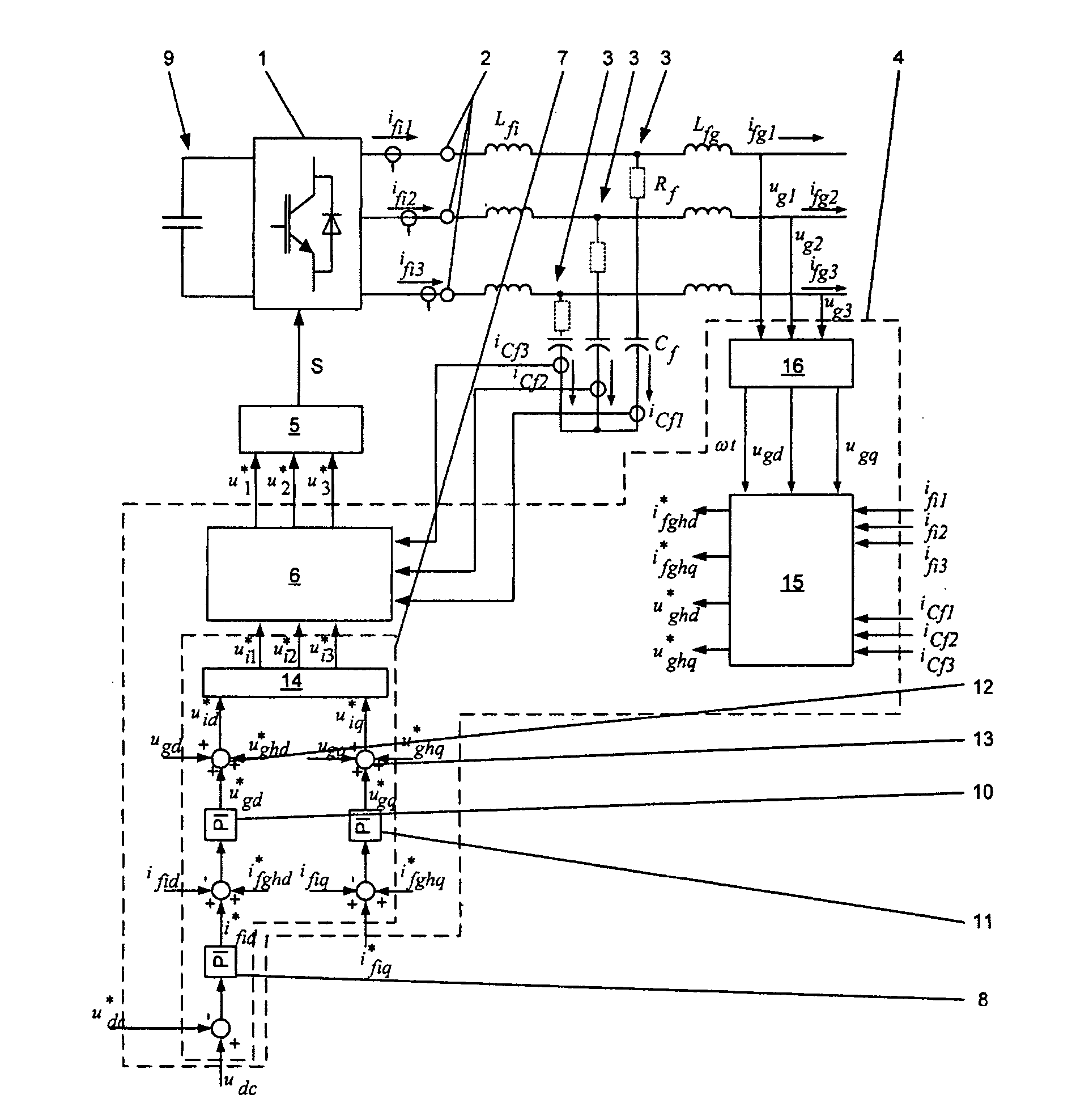
[0014]FIG. 1 shows one exemplary embodiment of an apparatus for carrying out an exemplary method for operation of a converter circuit. As shown in FIG. 1, the converter circuit has a converter unit 1 with a multiplicity of drivable power semiconductor switches and an LCL filter 3, which is connected to each phase connection 2 of the converter unit 1. Each LCL filter 3 accordingly has a first filter inductance Lfi, a second filter inductance Lfg as well as a filter capacitance Cf, with the first filter inductance Lfi being connected to the associated phase connection 2 of the converter unit 1, to the second filter inductance Lfg and to the filter capacitance Cf. Furthermore, the filter capacitances Cf of the individual LCL filters 3 are connected to one another. Each LCL filter 3 typically has a virtually negligible filter resistance Rf, which is connected in series with the filter capacitance Cf of the associated LCL filter 3 and represents resistive losses in the LCL filter 3. By w...


PUM


Abstract

A method for operation of a converter circuit is specified, wherein the converter circuit has a converter unit with a multiplicity of drivable power semiconductor switches and an LCL filter which is connected to each phase connection of the converter unit, in which method the drivable power semiconductor switches are driven by means of a drive signal which is formed from reference voltages. The reference voltages are formed by subtraction of damping voltages from reference-phase connection voltages, with the damping voltages being formed from filter capacitance currents, weighted with a variable damping factor of the LCL filter. An apparatus for carrying out the method is also specified.

Description

RELATED APPLICATIONS [0001] This application claims priority under 35 U.S.C. §119 to U.S. Provisional Application 60 / 646,544 filed in USA on Jan. 25, 2005, and as a continuation application under 35 U.S.C. §120 to PCT / CH2005 / 000293 filed as an International Application on May 24, 2005, designating the U.S., the entire contents of which are hereby incorporated by reference in their entireties.TECHNICAL FIELD [0002] The disclosure relates to the field of power electronics, and is based on a method for operation of a converter circuit, as well as an apparatus for carrying out the method.BACKGROUND INFORMATION [0003] Known converter circuits have a converter unit with a multiplicity of drivable power semiconductor switches, which are connected in a known manner in order to switch at least two switching voltage levels. An LCL filter is connected to each phase connection of the converter unit. A capacitive energy store is also connected to the converter unit, and is normally formed by one...

Claims


Application Information

Patent Timeline
IPC IPC(8): H02M1/12
CPCH02J7/345H02M7/53871H02M3/158H02M1/12
Inventor PONNALURI, SRINIVASSTEINKE, JURGEN
Owner ABB (SCHWEIZ) AG
Why Eureka
Try Eureka