Method of Programming Flash Memory Device

Inactive Publication Date: 2007-11-15
SK HYNIX INC
View PDF5 Cites 4 Cited by
  • Summary
  • Abstract
  • Description
  • Claims
  • Application Information

AI Technical Summary

Benefits of technology

[0015]Accordingly, this patent addresses the above problems, and discloses a method of programming a flash memory device, in which it can improve th

Problems solved by technology

The cell threshold voltage that is distributed widely as described above degrades the read margin of the single level cell or the mu

Method used


Image

  • Method of Programming Flash Memory Device
  • Method of Programming Flash Memory Device
  • Method of Programming Flash Memory Device

Examples


Embodiment Construction

[0036]Now, various embodiments will be described with reference to the accompanying drawings. Because various embodiments are provided for the purpose that the ordinary persons skilled in the art are able to understand the present patent, they may be modified in various manners and the scope of the present patent is not limited by the various embodiments described later.

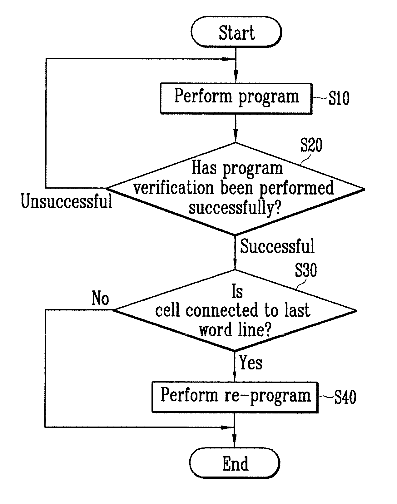
[0037]FIG. 3 is a flowchart illustrating a method of programming a flash memory device according to an embodiment of the present invention. FIGS. 4 to 6 are schematic circuit diagrams of cell strings for illustrating bias conditions at the time of a main program, program verification and re-program, respectively, in a method of programming a flash memory device according to an embodiment of the present invention. A method of programming a flash memory device according to an embodiment of the present invention will be described below with reference to FIGS. 4 to 6.

[0038]Referring to FIG. 3, a program is performed on a...


PUM


Abstract

At the time of a program of a NAND flash memory device, a re-program is performed on a cell connected to the last word line after program and program verification are completed. Thus, threshold voltage distributions of the cell connected to the last word line can be controlled to have a narrow width in the same manner as that of other cells. It is therefore possible to secure the read margin of a chip and to improve the yield. Accordingly, the durability and reliability of devices can be improved by threshold voltage distributions controlled to have a narrow width as described above.

Description

BACKGROUND[0001]1. Technical Field[0002]This patent relates, in general, to a method of programming a flash memory device and, more particularly, to a method of programming a flash memory device, in which threshold voltage distributions of a cell connected to the last word line can be controlled to have a narrow width.[0003]2. Discussion of Related Art[0004]In recent years, there is an increasing demand for semiconductor memory devices which can be electrically programmed and erased and does not require a refresh function of rewriting data at regular intervals. Furthermore, to develop memory devices with a large capacity capable of storing lots of data, a high-integrated technique of memory cells has been developed. To increase the integration of the memory cells, a NAND flash memory device in which a plurality of cells are connected in series to form one string and two strings share one contact has been developed.[0005]The NAND flash memory device includes a plurality of cell block...

Claims


Application Information

Patent Timeline
IPC IPC(8): G11C11/34
CPCG11C16/344G11C16/3459G11C16/3454G11C16/3445G11C16/10
Inventor LEE, MIN KYU
Owner SK HYNIX INC
Why Eureka
Try Eureka