Circuit and method for generating power up signal

Active Publication Date: 2006-10-05
SK HYNIX INC
View PDF10 Cites 8 Cited by
  • Summary
  • Abstract
  • Description
  • Claims
  • Application Information

AI Technical Summary

Benefits of technology

[0014] It is, therefore, an object of the present invention to provide a circuit for generating a power up signal, wherein a circuit design is improved to reduce a variation degree

Problems solved by technology

Provided the external power voltage Vext becomes unstable because of a noise or the like, the internal power voltage becomes unstable also.
At this time, a recovery for the external power voltage Vext can be rapidly done by driving a large driver out of the chip but a recovery for the internal voltage is very slow because only small driver is incorporated in

Method used


Image

  • Circuit and method for generating power up signal
  • Circuit and method for generating power up signal
  • Circuit and method for generating power up signal

Examples


first embodiment

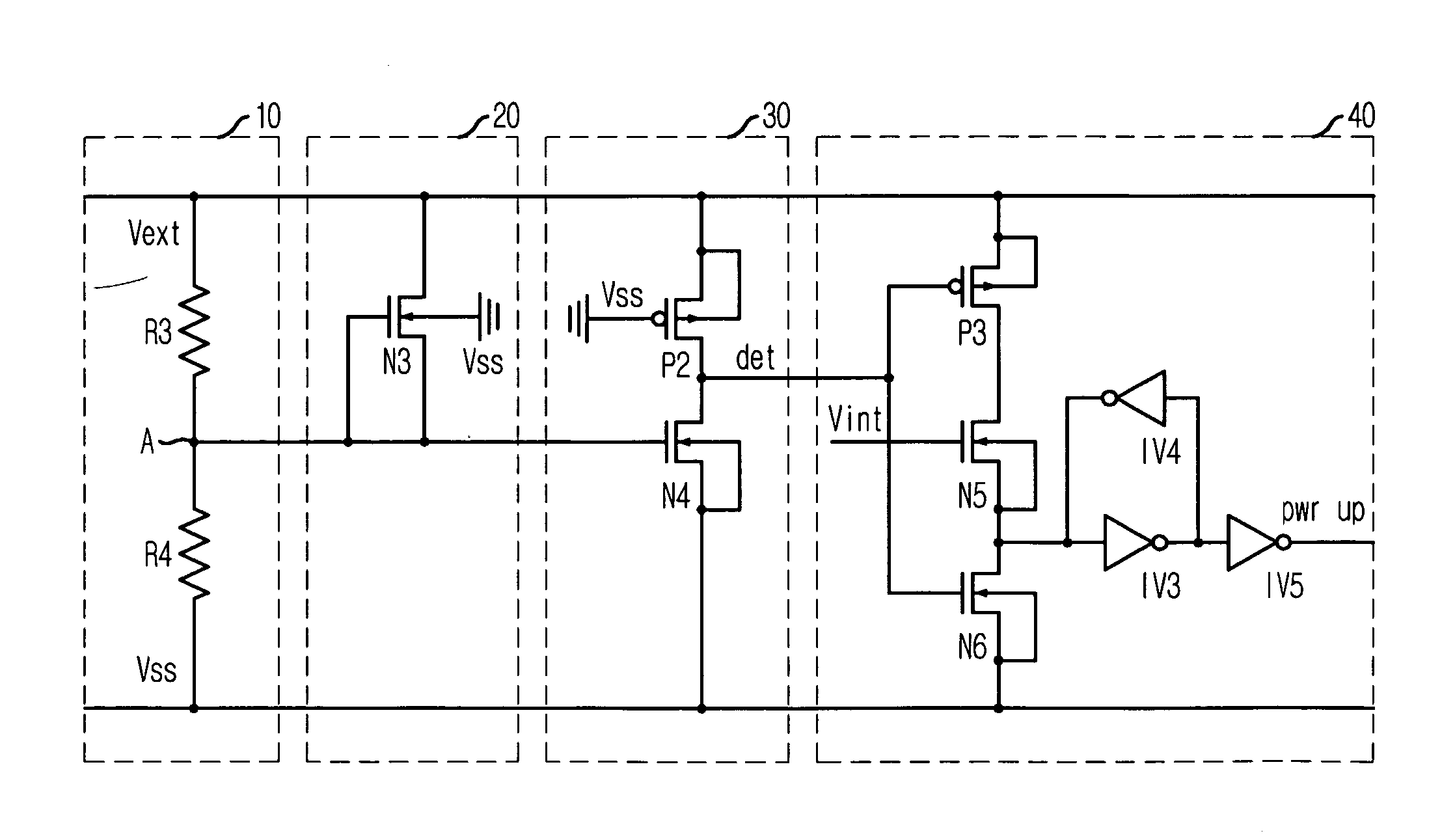
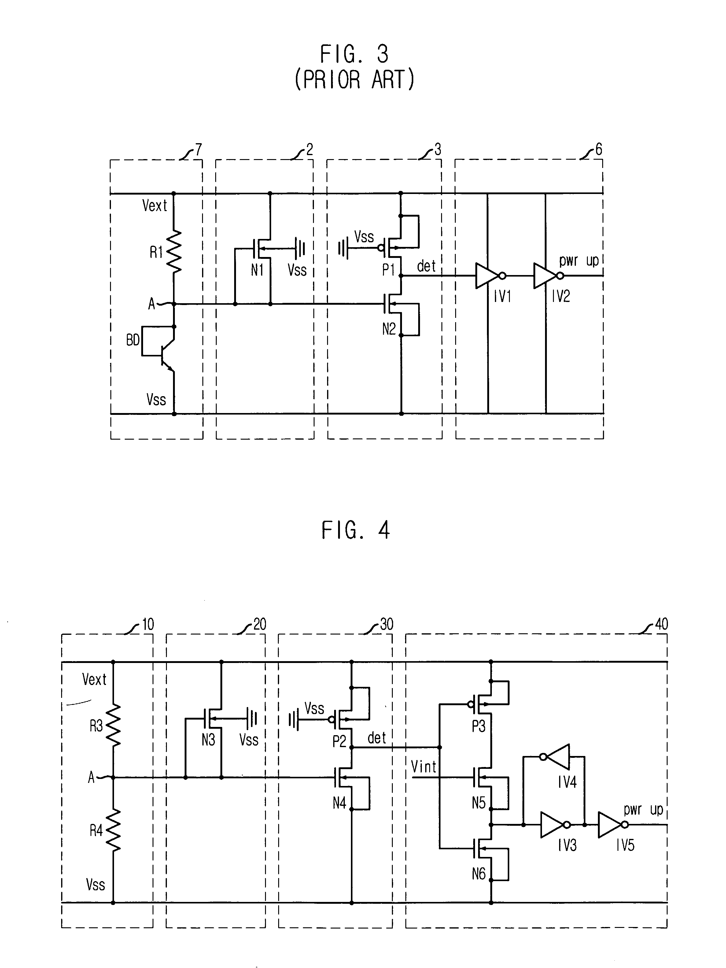
[0027]FIG. 4 is a circuit diagram setting forth a circuit for generating a power up signal in accordance with the present invention.

[0028] Referring to FIG. 4, the circuit for generating a power up signal includes an external power voltage divider 10, a level controller 29, an external power voltage detector 30 and a power up signal generator 40.

[0029] The external power voltage divider 10 divides the external power voltage Vext of which a level rises up with the lapse of the time by a predetermined ratio so as to output the divided voltage to detect a magnitude variation of the external power voltage Vext. The external power voltage divider 10 is provided with resistors R3 and R4 to divide the external power voltage Vext according to a resistance ratio between the resistors R3 and R4. At this time, the output voltage of the external power voltage divider 10 becomes a value expressed as a following equation, i.e., R4 / (R3+R4)*Vext.

[0030] The level controller 20 is operated if the o...

second embodiment

[0037]FIG. 5 is a circuit diagram setting forth a circuit for generating a power up signal in accordance with the present invention.

[0038] Referring to FIG. 5, in comparison with the circuit for generating the power up signal of the first embodiment, constitutions of an external power voltage divider 50 and a power up signal generator 60 are different from those in the first embodiment. That is, the external power voltage divider 50 of the second embodiment employs an NMOS diode ND instead of the resistor R4 for dividing the external power voltage Vext. In addition, the power up signal generator 60 further includes an inverter IV6 at an input terminal where the detection signal det is inputted. The other constitutions of the second embodiment are identical to those of the first embodiment so that like reference numerals in FIG. 5 denote like element in FIG. 4, and thus their descriptions will be omitted herein.

[0039] The power up signal generator 60 of the second embodiment activat...

third embodiment

[0041]FIG. 6 is a circuit diagram setting forth a circuit for generating a power up signal in accordance with the present invention.

[0042] Referring to FIG. 6, elements and constitutions of the apparatus in accordance with the third embodiment are same with those of the second embodiment except that a bipolar junction transistor (BJT) diode BD is used instead of the NMOS diode ND. Therefore, its operational principle is also same with that of the second embodiment so that further detail descriptions will be omitted herein.


PUM


Abstract

There is provided a circuit and a method for generating a power up signal. The circuit for generating a power up signal, includes an external power voltage divider for dividing a magnitude of an external power voltage so as to output the divided voltage, an external power voltage detector for activating a detection signal when the output voltage of the external power voltage divider reaches a preset level, and a power up signal generator for outputting a power up signal according to the detection signal and a first internal power voltage. Herein, the power up signal is generated when the internal power voltage as well as the external power voltage reaches a sufficient level so that a power up signal skew may be reduced to stabilize its operation and enhance reliability of a device.

Description

FIELD OF THE INVENTION [0001] The present invention relates to a circuit and a method for generating a power up signal; and more particularly, to a circuit and a method for generating a power up signal, in which the power up signal is generated after both levels of an external power and an internal power are stabilized enough by using the internal power as well as the external power. DESCRIPTION OF RELATED ART [0002] A power up circuit generates a power up signal after detecting whether a bulk bias voltage Vbb has secured a desired level or not. In addition, the power up circuit controls a semiconductor device till internal power voltages are stabilized to predetermined levels and a set-up operation is completely done. [0003] In general, a DRAM chip has a predetermined threshold voltage Vt in virtue of a PMOS transistor and an NMOS transistor incorporated therein while an external power voltage Vext rises up from 0 V to a target level. Therefore, an operational range of the DRAM chi...

Claims


Application Information

Patent Timeline
IPC IPC(8): H03L7/00
CPCH03K17/223G11C5/143E02D29/125E02D29/14
Inventor BYEON, SANG-JINPARK, KEE-TEOK
Owner SK HYNIX INC
Why Eureka
Try Eureka