
Wireless communication system and wireless communication method

a wireless communication and wireless communication technology, applied in the field of wireless communication system and wireless communication method, can solve the problems of affecting demodulation characteristics, channel estimation accuracy based on pilot symbols to be degraded, and the estimation precision of channel estimation values used in data demodulation has not been improved, so as to achieve the effect of improving channel estimation accuracy

Inactive Publication Date: 2007-11-15
FUJITSU LTD
View PDF7 Cites 40 Cited by
  • Summary
  • Abstract
  • Description
  • Claims
  • Application Information

AI Technical Summary

Benefits of technology

[0011] In light of the above, an object of the invention is to adaptively perform insertion of added pilot symbols based on the propagation path state, to improve channel estimation precision.
[0012] A further object of the invention is to adaptively improve channel estimation precision even when motion velocity is high and the fading frequency is high.

Problems solved by technology

However, at a cell edge there is the effect of interference from other cells, and so there is a tendency for channel estimation precision based on the pilot symbols to be degraded due to interference from other cells.
In this way, in conventional packet transmission methods the communication quality in the data channel between a user terminal at a cell edge or similar with poor communication quality and a base station is ensured through adaptive wireless link control, but there have existed no mechanisms for performing adaptive control of the pilot symbols, which greatly affect demodulation characteristics.
Hence the estimation precision of channel estimation values used in data demodulation has not been improved, and so there has been the problem of a limit to improvement of the demodulation characteristics of the data channel.
However, in the first technology of the prior art, the insertion of additional pilot symbols is not performed adaptively.
And in the first technology of the prior art, the properties particular to the 3GPP standard are utilized, so that general application to channel estimation for wireless communication is not possible.
The second technology of the prior art is not a method of adaptive insertion of additional pilot symbols, but of always inserting pilot symbols into the preamble portion and into the payload portion, so that there is the problem that the number of pilot symbols increases and transmission efficiency is reduced.

Method used


Image

  • Wireless communication system and wireless communication method
  • Wireless communication system and wireless communication method
  • Wireless communication system and wireless communication method

Examples


first embodiment

(B) First Embodiment

[0068] (a) Configuration of Transmission Device

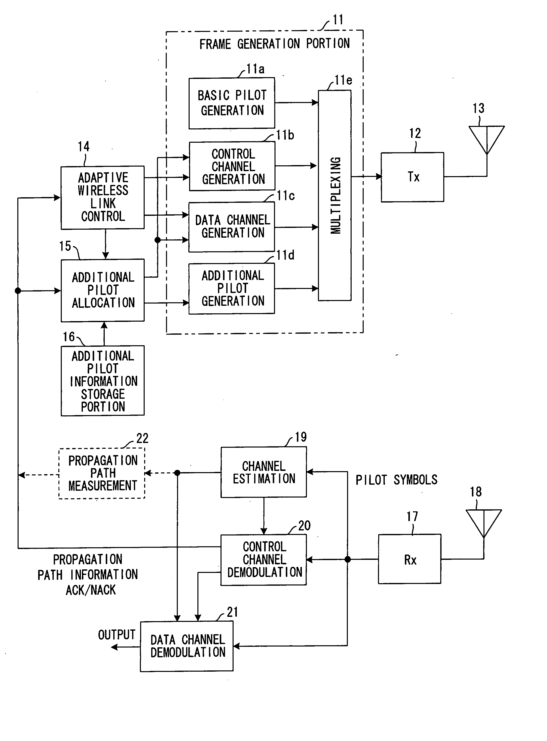
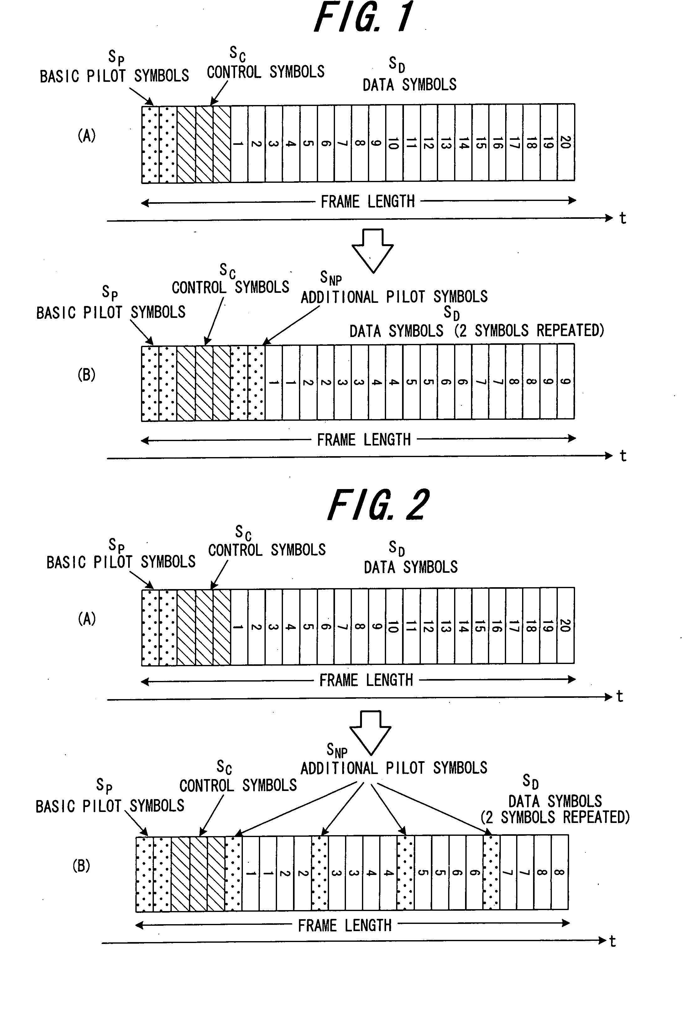
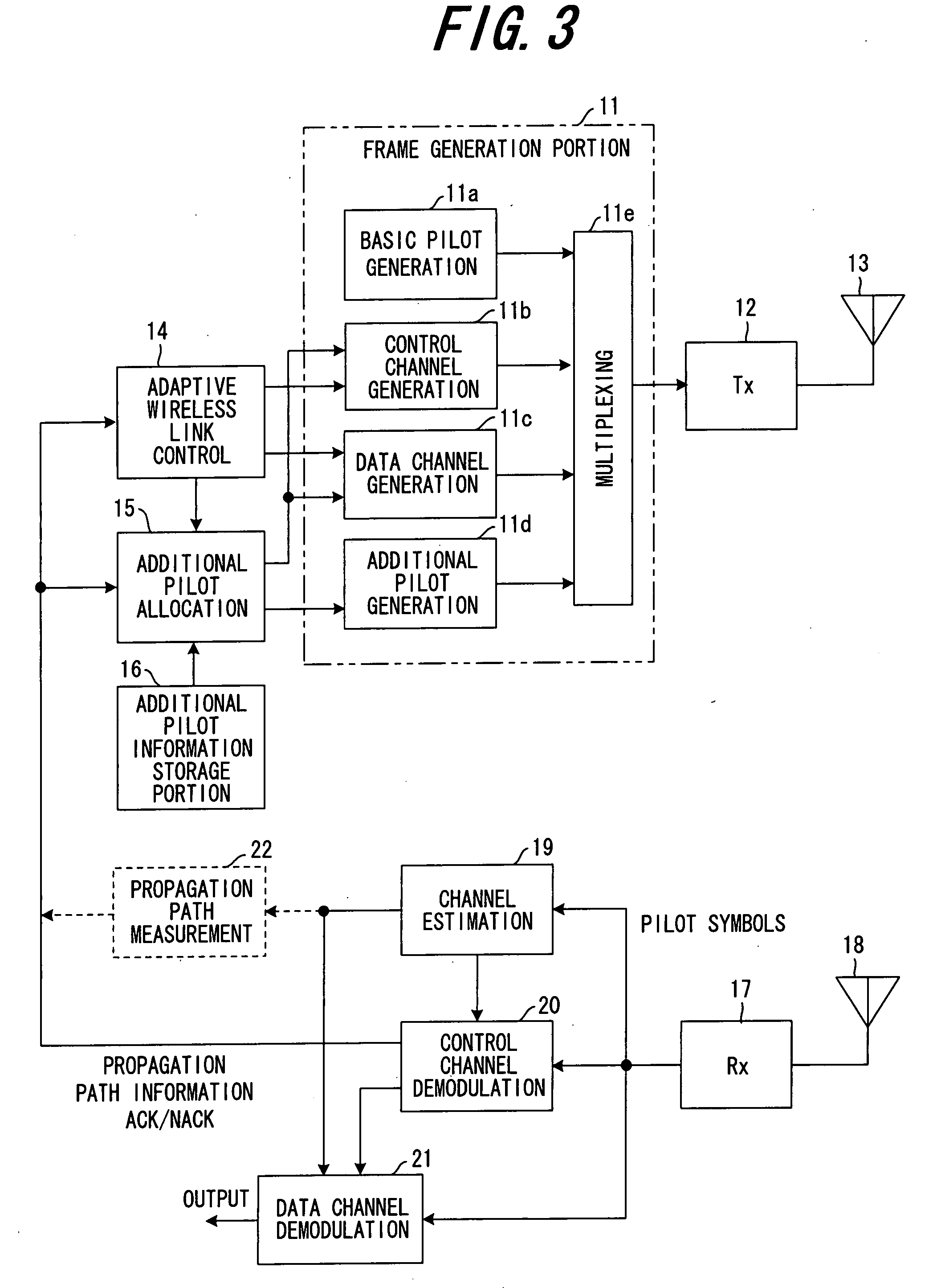
[0069]FIG. 3 shows the configuration of a transmission device of the invention; the frame generation portion 11 has a basic pilot generation portion 11a which generates basic pilot symbols, a control channel generation portion 11b which generates control symbols, a data channel generation portion 11c which generates data symbols, an additional pilot generation portion 11d which generates additional pilot symbols, and a multiplexing portion 11e which performs multiplexing of these symbols. The frame generation portion 11 generates a frame such as that shown in (A) of FIG. 1 and (A) of FIG. 2 when additional pilot symbols SNP are not added, and generates a frame such as shown in (B) of FIG. 1 or in (B) of FIG. 2 when additional pilot symbols SNP are to be added, and outputs the frame. The transmission portion 12 orthogonally modulates frames generated by the frame generation portion 11, and up-converts the baseband tr...

second embodiment

(C) Second Embodiment

[0126]FIG. 15 shows the configuration of the transmission device in a second embodiment; the device has a configuration enabling both transmission using a single transmission antenna, and MIMO multiplexed transmission.

[0127] In the event of MIMO multiplexed transmission, the transmission device uses two transmission antennas 51, 52, transmitting independent data channels from the transmission antennas 51, 52; when MIMO multiplexed transmission is not performed, a data channel is transmitted only from transmission antenna 51.

[0128] The first frame generation portion 53 assembles a frame not comprising additional pilot symbols, to be transmitted from one transmission antenna 51, and the second frame generation portion 54 assembles a frame to be transmitted from the other transmission antenna 52, comprising additional pilot symbols, but not comprising basic pilot symbols or control symbols.

[0129] That is, the frame generation portion 53 comprises a basic pilot g...

third embodiment

(D) Third Embodiment

[0143]FIG. 18 shows the configuration of the transmission device of a third embodiment, capable of both transmission by only a single transmission antenna, and of transmission using a plurality of antennas for transmission-beam forming. The beam directionality of one antenna ANT1 is nondirectional, as indicated by BD1 in FIG. 19, and the gain is constant regardless of the direction from ANT1 to the mobile terminal MS. On the other hand, by means of an adaptive array antenna, the transmission beam can be provided with the directionality BD2 and transmission can be directed in a prescribed direction, so that compared with a case of nondirectional transmission by a single antenna, a higher gain can be obtained. Hence when the mobile terminal MS becomes distant from the antenna ANT1 and reception quality declines, through transmission-beam forming to perform transmission from a plurality of antennas with directionality, the reception quality can be improved.

[0144] T...


PUM


Abstract

On the transmitting side, a decision is made as to whether to add pilot symbols which are separate from basic pilot symbols, to frames, based on the propagation path state, and when symbols are added, control symbols comprising information relating to the additional pilot symbols are generated, and frames comprising basic pilot symbols, control symbols, additional pilot symbols, and data symbols are assembled and transmitted. On the receiving side, control symbols included in the received frames are demodulated, and a judgment is made as to whether additional pilot symbols are included in the received frames based on the control symbol information, and if additional pilot symbols are included, the additional pilot symbols are used to estimate the propagation path, and the propagation path estimation value is used to demodulate data symbols.

Description

BACKGROUND OF THE INVENTION [0001] This invention relates to a wireless communication system and wireless communication method, and in particular relates to a wireless communication system and wireless communication method for transmitting and receiving frames comprising basic pilot symbols used for propagation path estimation, control symbols which convey control information necessary for data channel demodulation, and data symbols which convey information bits. [0002] In order to increase the efficiency of data packet transmission in packet transmission for cellular mobile communication, adaptive modulation / demodulation control, adaptive spreading factor control, transmission power control, HARQ (Hybrid Automatic Repeat reQuest) control, scheduling control, and other types of adaptive wireless link control are employed. These types of control are performed using a control channel which is transmitted with the data channel; the transmitting station uses the control channel to notif...

Claims


Application Information

Patent Timeline
Patent Type & Authority Applications(United States)
IPC IPC(8): H04L27/00H04B1/707H04B1/7103H04B1/711H04J99/00
CPCH04L1/0006H04L1/0015H04L1/0026H04L5/0007H04B7/2656H04L5/0051H04L5/0048H04L1/1671H04B1/76H04B7/0617
Inventor SEKI, HIROYUKI
Owner FUJITSU LTD
Learn More