Uniform Switching System and Method for Synchronous Optical Network and Optical Transport Network

a technology of optical communication network and uniform switching, applied in the direction of multiplex communication, time-division multiplex, electrical apparatus, etc., can solve the problems of not being able to uniformly switch well not being able to achieve uniform switching, etc., to achieve the effect of reducing the requirements of system performance, improving the performance of switching, and being easy to implemen

Inactive Publication Date: 2007-11-15
HUAWEI TECH CO LTD
View PDF9 Cites 36 Cited by
  • Summary
  • Abstract
  • Description
  • Claims
  • Application Information

AI Technical Summary

Benefits of technology

[0087] Compared with the prior art, the technical solutions of the invention are simpler and easier to be implemented because the system design and the cross design according to the embodiments of the invention are simpler.
[0088] Because the STM-17 bus is connected to the cross-connecting unit through the uniform frame header indication signal, the time for switching between the main / backup units may be at the overhead position of the STM-17 bus, thus hit to service is avoided and the performance of the switching is improved greatly. Moreover, as the asynchronous mapping is used for the OTN signal, and specifically, the ODU pointer and the adjustment position are introduced at a fixed position in the VC4 when the OTN signal is mapped, the system may directly map an OTN signal without large buffer space, which decreases the requirements for the system performance and thus reduces the system cost.
[0089] In the embodiment of the invention, the interworking between an SDH and an OTN may be implemented because the uniform switching is performed after an SDH signal and an OTN signal are mapped into the STM-17 bus uniformly, thus it is easier to upgrade the SDH to the OTN smoothly and expand the services.
[0090] The bus may be monitored to avoid an error and thus improve the reliability of the system greatly because the STM-17 bus has frame synchronization bytes and error code monitoring bytes.

Problems solved by technology

In practical applications, the inventor finds that, by the conventional methods above, the OTN signal is not switched well, the signals in the SDH and the OTN are not uniformly switched well either.
In the first conventional method, equivalent ODU2 / ODU3 serial signals cannot be switched, the switching path and the cross design are complex, and neither the lossless switch of main / backup cross units nor the uniform switching of SDH signals and OTN signals can be implemented.
In the third conventional method, a large buffer space is needed and the third conventional method is difficult to be realized technically, furthermore, the utilization of the bus may become very low.
With respect to the first conventional method, the switching of equivalent ODU2 / ODU3 serial signals cannot be implemented because the asynchronous cross chip technology is not mature yet and the industry cannot provide a large capacity asynchronous electrical cross network chip at the 43 Gbps / 10.7 Gbps granularity level.
Moreover, the switching path is complex because of the coupling relations between the matrixes of various levels, and the cross design is complex because of the three-level asynchronous cross matrixes.
There is loss when the main / backup cross units are switched because the asynchronous cross mode is adopted.
Moreover, the uniform switching of SDH signals and OTN signals cannot be implemented by the first conventional method, only OTN signals can be switched by the first conventional method.
Because the frame header of the ODU signal is not consistent with that of the SDH signal, the frame header of the ODU signal is required to wait for the frame header of the SDH signal, thus a delay less than the time of transferring one frame is brought about to the ODU signal, and the feature of short delay of the OTN network cannot be realized.

Method used


Image

  • Uniform Switching System and Method for Synchronous Optical Network and Optical Transport Network
  • Uniform Switching System and Method for Synchronous Optical Network and Optical Transport Network
  • Uniform Switching System and Method for Synchronous Optical Network and Optical Transport Network

Examples


Embodiment Construction

[0101] In the invention, the SDH signal is synchronized with the system clock and adapted into the synchronous transfer mode bus, such as an STM-17 bus. And the OTN signal is mapped into the STM-17 bus asynchronously based on a certain rule. The cross-connection of the signal of the STM-17 bus is performed at a uniform rate level of the synchronous transfer mode, such as the STM-1 or the VC4, so as to implement the interworking between the SDH and the OTN. Moreover, the technical solutions of the invention may also be applied directly to a pure OTN, no SDH signal is processed and only the OTN signal is mapped into the STM-17 bus to be switched.

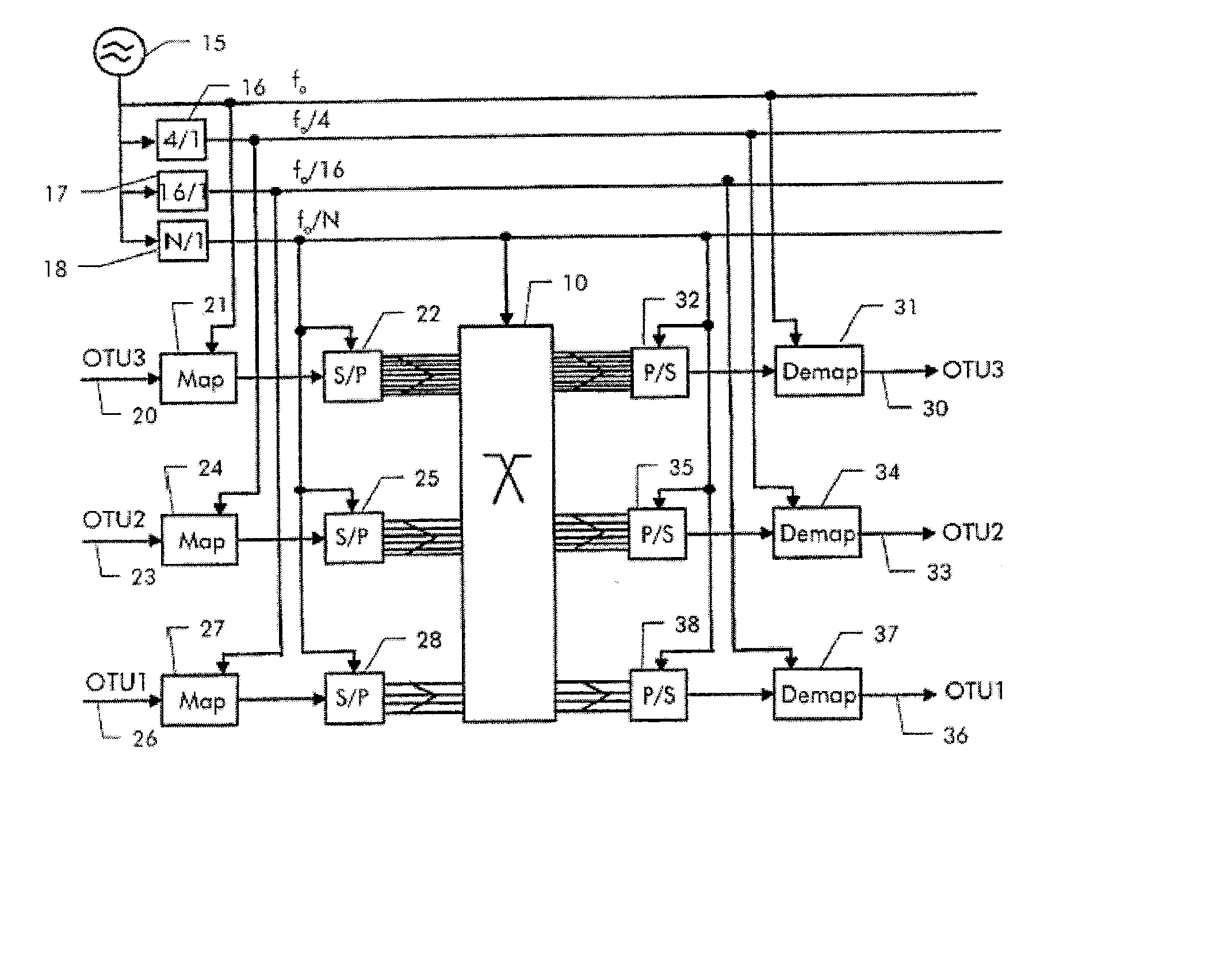
[0102]FIG. 7 shows a schematic diagram of the structure of the OTN switching system in accordance with an embodiment of the invention.

[0103] As shown in FIG. 7, the OTN switching system includes: system clock unit 10, SDH signal interface processing unit 20, OTN signal interface processing unit 30 and cross-connection unit 40. The system clo...


PUM


Abstract

Embodiments of the invention provide a method and a system for switching an OTN signal using the SDH. The system includes a system clock unit for providing a system clock signal and a frame header indication signal, a cross-connection unit for performing signal cross-connection at a uniform level of synchronous transfer mode rate, and an OTN signal interface processing unit for mapping, based on the system clock signal and frame header indication signal provided by the system clock unit, an OTN signal received from the circuit side into a synchronous transfer mode bus to be sent to the cross-connection unit, and de-mapping a signal output by the cross-connection unit through the synchronous transfer mode bus to an OTN signal to be output to the circuit side. An OTN signal may be switched in the SDH and the service interworking between an SDH network and an OTN may be achieved.

Description

CROSS-REFERENCE TO RELATED APPLICATIONS [0001] This is a continuation of International Application No. PCT / CN2005 / 002184, filed Dec. 14, 2005, which claims the benefit of Chinese Patent Application No. CN200410103304.7, filed Dec. 14, 2004, the entire disclosure of which is incorporated herein by reference.BACKGROUND OF THE INVENTION [0002] 1. Field of the Technology [0003] The invention relates to the technologies of signal switching in an optical communication network, and particularly, to the technology of signal switching in an optical communication network with an optical transport network. [0004] 2. Background of the Technology [0005] The technology of Optical Transport Hierarchy (OTH) is a new standard digital transport hierarchy developed after the Synchronous Digital Hierarchy (SDH) / Synchronous Optical Network (SONET). The Optical Transport Network (OTN) based on the OTH is a transparent transport technology developed to meet the demand of large capacity and large granulari...

Claims


Application Information

Patent Timeline
Patent Type & Authority Applications(United States)
IPC IPC(8): H04J14/00
CPCH04J3/0685H04J2203/0021H04J3/1611
Inventor LI, XIAODONGZOU, SHIMIN
Owner HUAWEI TECH CO LTD
Why Eureka
Try Eureka