Suction device for a pick power tool

a technology of suction device and power tool, which is applied in the direction of percussive tools, manufacturing tools, transportation and packaging, etc., can solve the problem of limited aspiration size of removed material pieces, and achieve the effect of preventing the blockage of suction lines

Active Publication Date: 2007-11-15
HILTI AG
View PDF23 Cites 31 Cited by
  • Summary
  • Abstract
  • Description
  • Claims
  • Application Information

AI Technical Summary

Benefits of technology

[0016] The retaining element is preferably formed by a wall portion which has the through-opening for the working tool and which has the at least one well-defined suction opening, the latter being circumferentially closed. The wall portion closes the suction device in the area of the second end and, by a corresponding construction of the through-opening, ensures the guidance of the suction device along the working tool and a sufficient suction of the occurring dust and pieces of removed material through the at least one suction opening.
[0017] The at least one suction opening preferably has a substantially circular cross section so that the size of the particles aspirated to the suction device can be controlled in an advantageous manner.
[0018] The retaining element is preferably formed by a grating portion which has the through-opening for the working tool and whose meshes form the suction openings. The grating portion covers the area of the second end and, by a corresponding construction of the through-opening, ensures the guidance of the suction device along the working tool and a sufficient suction of the occurring dust and pieces of removed material through the suction openings.
[0019] The retaining element preferably has a plurality of ribs which are spaced apart from one another and extend from an out...

Problems solved by technology

Due to the design of the at least one suction opening, the maximum size of the aspirate...

Method used


Image

  • Suction device for a pick power tool
  • Suction device for a pick power tool
  • Suction device for a pick power tool

Examples


Embodiment Construction

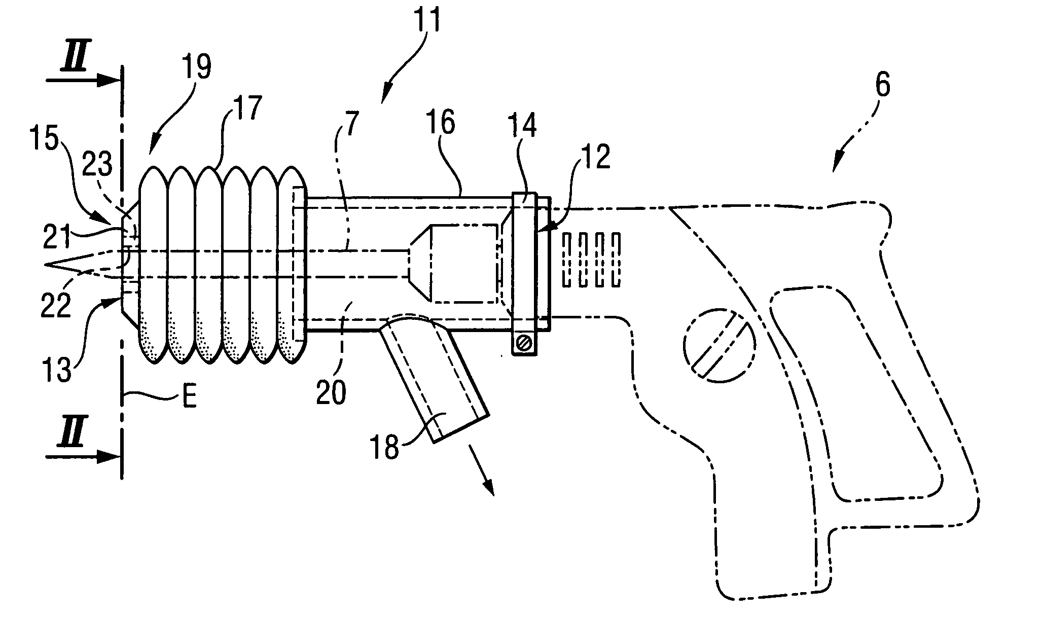
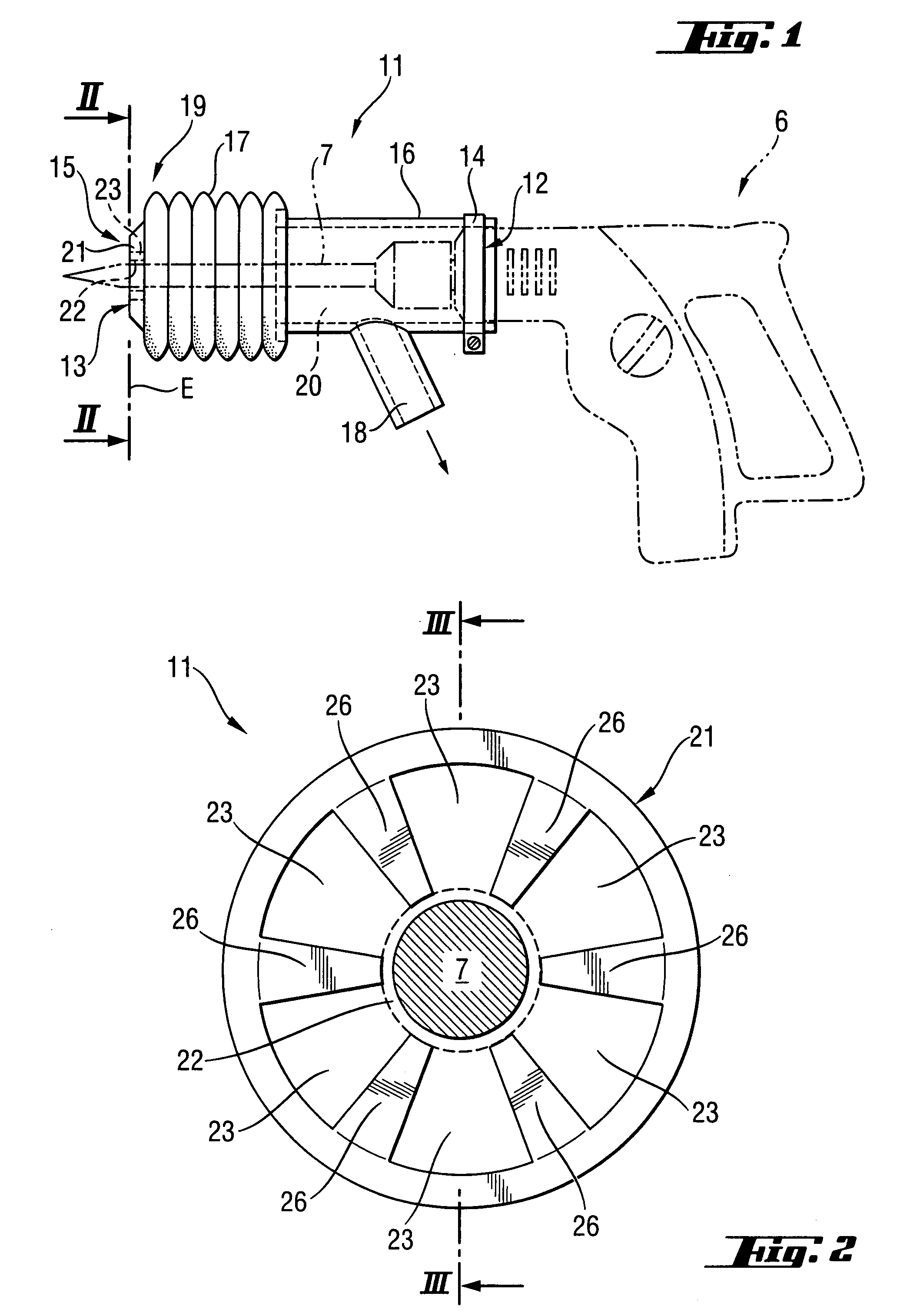
[0032] The suction device 11 shown in FIGS. 1 to 3 is arranged at a pick power tool 6 formed as a combi-hammer. A securing device 14 in the form of a collar band for detachably securing the suction device 11 to the pick power tool 6 is provided at a first end 12 of the suction device 11. At its second end 13, the suction device 11 has a contact area 15 with which the suction device 11 contacts a constructional component. The suction device 11 has a rigid portion 16 which extends from the first end 12 in direction of the second end 13, and a flexible portion 17 which extends from the rigid portion 16 to the second end 13 of the suction device 11 and which can be reduced in a longitudinal direction parallel to the longitudinal extension of the working tool 7. The rigid portion 16 and the flexible portion 17 form a receiving space 20 which partially encloses a working tool 7 arranged in the pick power tool 6. A connection piece for a vacuum source, not shown, is provided at the rigid p...


PUM

PropertyMeasurementUnit
Lengthaaaaaaaaaa
Lengthaaaaaaaaaa

Abstract

A suction device (11) for a hammer drill (6) has a first end (12) with a securing device (14) for securing the suction device (11) to the hammer drill (6) and a second end (13) opposite first end (12) and which has a contact area (15) with which the suction device (11) contacts a constructional component, the suction device (11) further having a receiving space (20) which at least partially encloses a working tool (7) of the pick power tool (6), and being provided with a connection device (18) for a vacuum source. A retaining element (21) having a through-opening (22) for the working tool (7) and a plurality of suction openings (23) is provided in an area (19) of the second end (13).

Description

BACKGROUND OF THE INVENTION [0001] 1. Field of the Invention [0002] The invention is directed to a suction device for a pick power tool including a suction device for a pick power tool, comprising a receiving space which at least partially encloses a working tool of the pick power tool, a securing device provided at a first end of the suction device for securing the suction device to the pick power tool, a contact area provided at a second end of the suction device opposite the first end for contacting a constructional component, a connection device for a vacuum source. [0003] 2. Description of the Prior Art [0004] When a mineral constructional component such as, for example, a concrete wall or concrete floor is worked by a working tool of a pick power tool such as a drill hammer, combi-hammer or chisel hammer, pieces of the broken material and dust occur. The dust particles, in particular, lead to a contamination of the environment, e.g., of interior spaces of a building, and imped...

Claims


Application Information

Patent Timeline
IPC IPC(8): B23B27/10B23B51/06B27C9/00
CPCB23B2270/30Y10T408/453B25D17/20B23Q11/0046
Inventor BLEICHER, JOCHENOHLENDORF, OLIVER
Owner HILTI AG
Why Eureka
Try Eureka