
Flexible and extendable drill bit assembly

Active Publication Date: 2007-11-15
WHITE CHRISTOPHER L +1
View PDF25 Cites 21 Cited by
  • Summary
  • Abstract
  • Description
  • Claims
  • Application Information

AI Technical Summary

Benefits of technology

[0004] Therefore it is an object of the invention to provide a flexible drill bit assembly that allows a user to change diameters of the drilling bit.

Problems solved by technology

Moreover, when the cutting edge is damaged, the entire drill bit must be replaced, incurring additional expense.

Method used


Image

  • Flexible and extendable drill bit assembly
  • Flexible and extendable drill bit assembly
  • Flexible and extendable drill bit assembly

Examples


Embodiment Construction

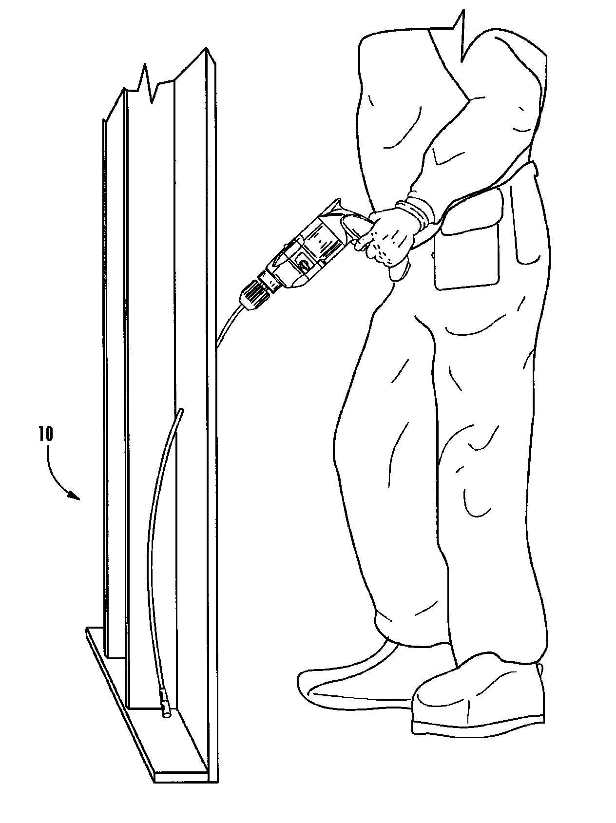
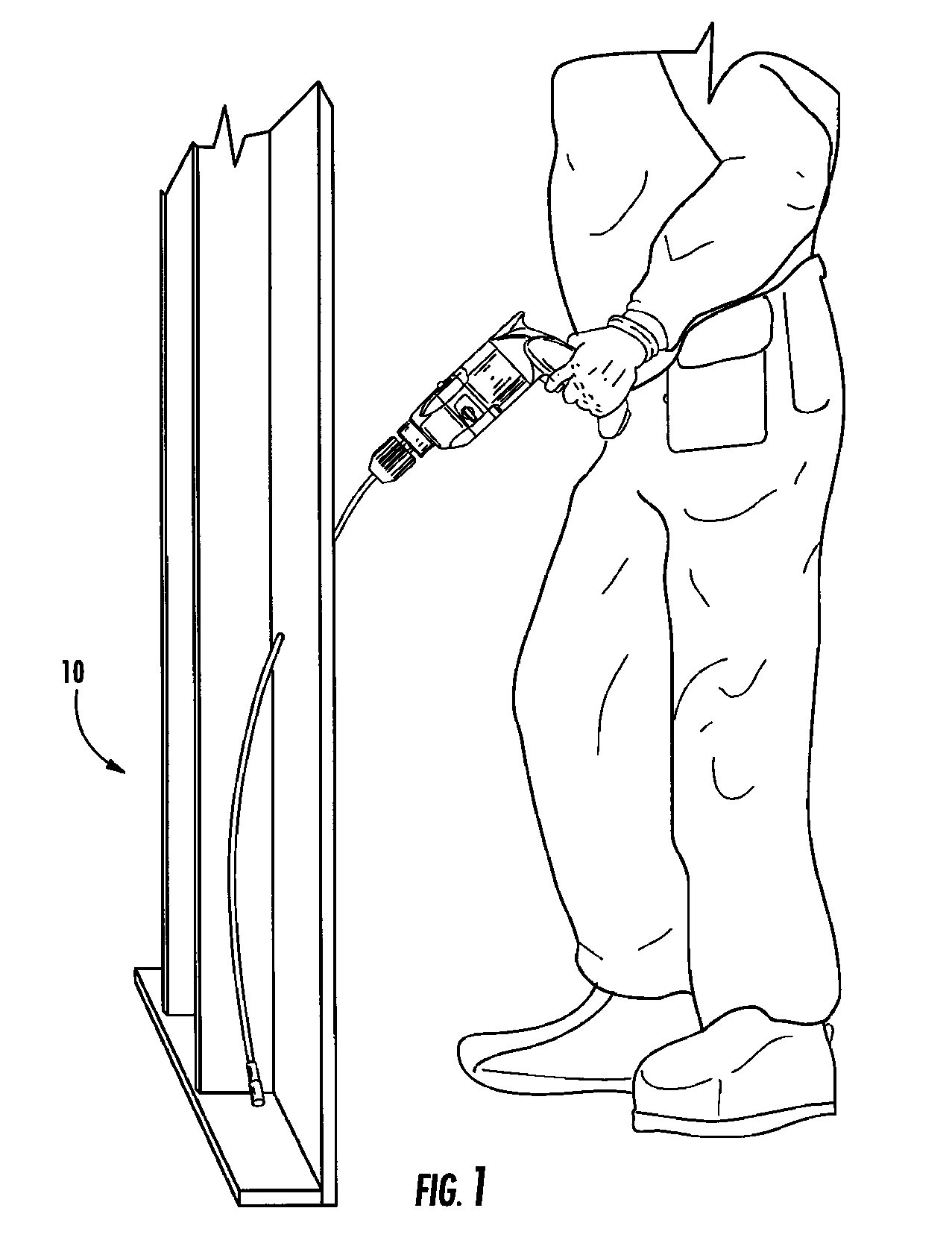
[0040] Referring now specifically to the drawings, a flexible, extendable drill bit assembly according to an embodiment of the invention is illustrated in FIG. 1 and shown generally at reference numeral 10. As shown, the drill bit assembly 10 allows a user to drill a hole through a wall to allow the user to run wiring and cabling.

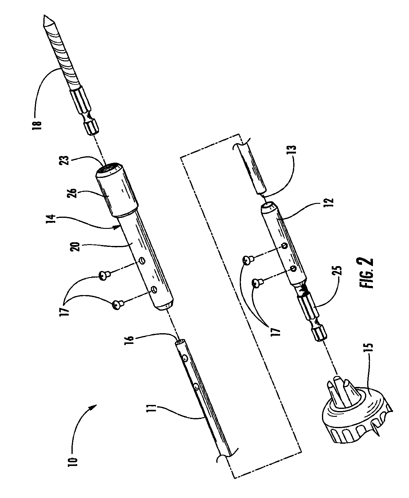
[0041] As shown in FIG. 2, the drill bit assembly 10 includes a flexible extension rod 11, a tailpiece 12 secured to a first end 13 of the rod 11 and adapted to be received by a drill 15, and a quick-release head 14 secured to an opposing second end 16 of the rod 11. The tailpiece 12 includes a shank 25 with a hexagonal profile to prevent slipping within the drill 15. As illustrated, the first and second ends 13 and 16 are received by the tailpiece 12 and head 14, respectively, and secured by set screws 17. It should be appreciated that the rod 11 may be secured to the tailpiece 12 and head 14 by any suitable fastening means, such as adhesives or welding. ...


PUM

PropertyMeasurementUnit
Diameteraaaaaaaaaa
Flexibilityaaaaaaaaaa

Abstract

A flexible, extendable extension assembly used to create extended length holes and holes through inaccessible areas in walls and framing. The extension assembly including a flexible rod having first and second ends; and a holding means secured to the first end of the rod for releasably holding a tool bit for rotation with the rod.

Description

TECHNICAL FIELD AND BACKGROUND OF THE INVENTION [0001] The present invention relates to the field of flexible drill bits used to create extended length holes and holes through inaccessible areas in walls and framing. More particularly, the invention relates to a flexible, extendable drill bit assembly that allows the use of a variety of drilling heads and accessories. [0002] Flexible, extended drill bits are widely employed to create a system of holes within residential and commercial building construction for the purpose of running extended wiring and cabling throughout the building. The extended length drill bits presently available are of a unitary construction, requiring a user to purchase a drill bit having a specified diameter for each individually sized hole desired. The drill bits come in various lengths which require a user to purchase a separate drill bit for each specified length of a hole. Moreover, when the cutting edge is damaged, the entire drill bit must be replaced,...

Claims


Application Information

Patent Timeline
IPC IPC(8): B23B45/00
CPCB23B45/005Y10T279/17752Y10T408/665B23B51/126
Inventor WHITE, CHRISTOPHER L.DAVIDIAN, RICHARD M.
Owner WHITE CHRISTOPHER L
Learn More