Pneumatic-aided fitness equipment

a technology of pneumatic aided fitness and equipment, which is applied in the direction of gymnastic exercise, editing/combining figures or text, instruments, etc., can solve the problems of shortening the life of the handgrip, easy to be loosened and damaged, and not being able to meet the demand of users

Inactive Publication Date: 2007-11-15
LIN RICHARD
View PDF12 Cites 17 Cited by
  • Summary
  • Abstract
  • Description
  • Claims
  • Application Information

AI Technical Summary

Benefits of technology

[0011] 1. The present invention uses a directional ring 80 placed on the end opening 120 of the horizontal tube 12 of the first handle 10. The directional ring 80 has several protruding blocks 81 spaced through out the surface of the end opening 120 of the horizontal tube 12, so that the end opening 120 of the horizontal tube 12 has several concave slots 121 spaced through out the surface for the protruding blocks 81 mentioned above to position. The

Problems solved by technology

The conventional positioning structure must have two semi-circular components combined at the end opening of the hollow tube, because the positioning structure cannot be fitted from the expanded piston.
The bi

Method used


Image

  • Pneumatic-aided fitness equipment
  • Pneumatic-aided fitness equipment
  • Pneumatic-aided fitness equipment

Examples


Embodiment Construction

[0025] The features and the advantages of the present invention will be more readily understood upon a thoughtful deliberation of the following detailed description of a preferred embodiment of the present invention with reference to the accompanying drawings.

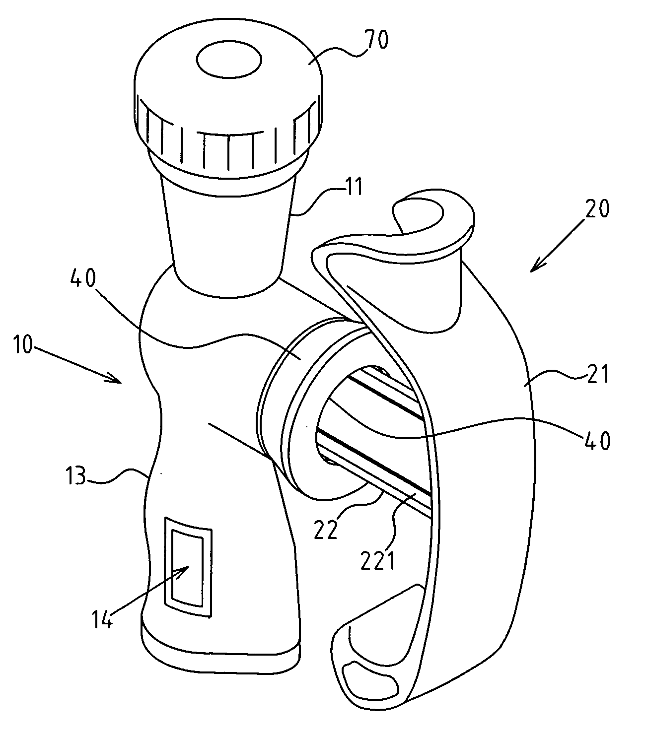
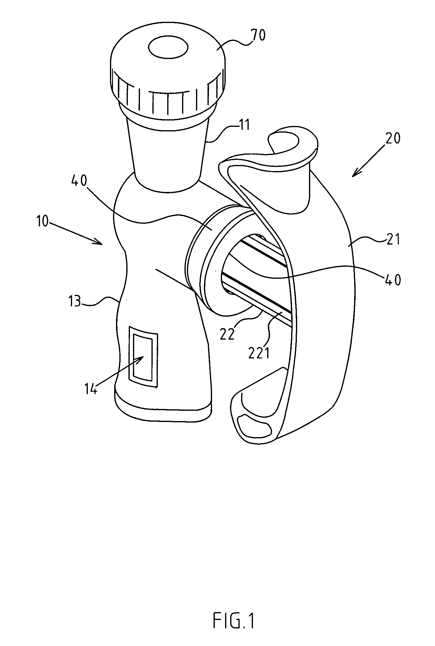
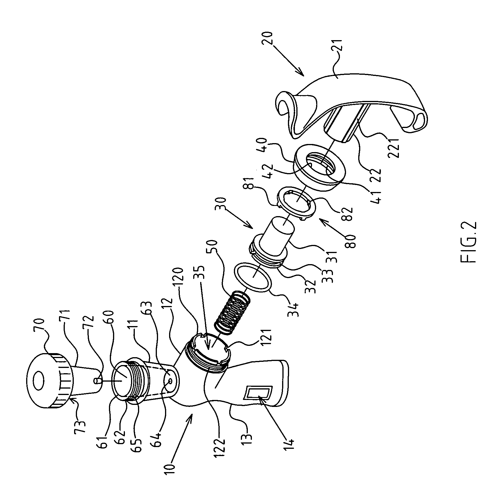
[0026] As shown in FIGS. 1-4, there is an improved structure of pneumatic-aided fitness equipment. The detailed description of the present invention is based on a typical preferred embodiment, placing no restriction on present invention except as claimed. The preferred embodiment of the pneumatic-aided fitness equipment is a fitness grip A.

[0027] The invention includes a first handle 10, which is in a T-shape with a vertical tube 11 and a horizontal tube 12. A grip surface 13 is placed on the outside of the vertical tube 11 for people's fingers to grip. The grip surface 13 can be shaped like waves for people to grab it tightly, and the horizontal tube 12 protrudes out in the middle of the vertical tube 11.

[0028] A second han...


PUM


Abstract

The structure of pneumatic aided fitness equipment includes a combined piston base at the piston made by the protruding tube of the second handle, which includes a protruding column and a piston, and the protruding column can be inserted and secured into to the protruding tube of the second handle. The piston can be slid inside the horizontal tube of the first handle. A limiting clamping ring includes a clamping part and a retracting hole, the limit clamping ring being positioned at an end opening of a horizontal tube of the first handle. The retracting hole is used for said protruding tube of the second handle, and a round edge is formed around the retracting hole to block the piston of the combined piston base. By so doing, the position of the piston of the second handle is more secure, durable and practical.

Description

RELATED U.S. APPLICATIONS [0001] Not applicable. STATEMENT REGARDING FEDERALLY SPONSORED RESEARCH OR DEVELOPMENT [0002] Not applicable. REFERENCE TO MICROFICHE APPENDIX [0003] Not applicable. FIELD OF THE INVENTION [0004] The present invention relates generally to an improved structure of pneumatic-aided fitness equipment, and more particularly to fitness equipment which has handle or pushing part, such as a handgrip or leg press. BACKGROUND OF THE INVENTION [0005] The fitness equipment of the present invention has a pneumatic aid, and the structure of the fitness equipment must have a handle or pushing part, such as a handgrip and leg press. For example, there is a conventional structure of the handgrip, the handgrip being fitness equipment that trains hands to control the muscle force. The conventional handgrips have pneumatic structures in an H-shape, and each handgrip is comprised of a first handle and second handle. The place where two handles connect has a piston inside the st...

Claims


Application Information

Patent Timeline
IPC IPC(8): A63B21/008
CPCA63B21/00072A63B21/0087A63B21/023A63B21/05G06T15/04A63B23/03525A63B23/16G06T11/60A63B21/1488A63B21/4045
Inventor LIN, RICHARD
Owner LIN RICHARD
Why Eureka
Try Eureka