Interleaver and De-Interleaver

a technology applied in the field of interleaver and decoder, can solve the problems of reducing the overall system throughput, affecting the accuracy of data transmission, and adding excessive overhead in terms of error detection information

Inactive Publication Date: 2007-11-15
BROADCOM INT PTE LTD
View PDF6 Cites 34 Cited by
  • Summary
  • Abstract
  • Description
  • Claims
  • Application Information

AI Technical Summary

Problems solved by technology

Detection and correction of higher numbers of errors, especially higher numbers of consecutive errors, may add excessive overhead in terms of error detection information (e.g., parity bits), reducing overall system throughput.
Errors in data at the receiver may be caused by incorrect decisions of the detection and/or decoding process because of signal degradation.
Signal degradation occurs from added random and/or burst noise as the signal passes through the communication channel.
For some product codes, the resulting output sequence may include symbol patterns that are particularly susceptible to detection error.
For example, a sequence of all “1's may be difficult to detect if the receiver's sampl...

Method used


Image

  • Interleaver and De-Interleaver
  • Interleaver and De-Interleaver
  • Interleaver and De-Interleaver

Examples


Embodiment Construction

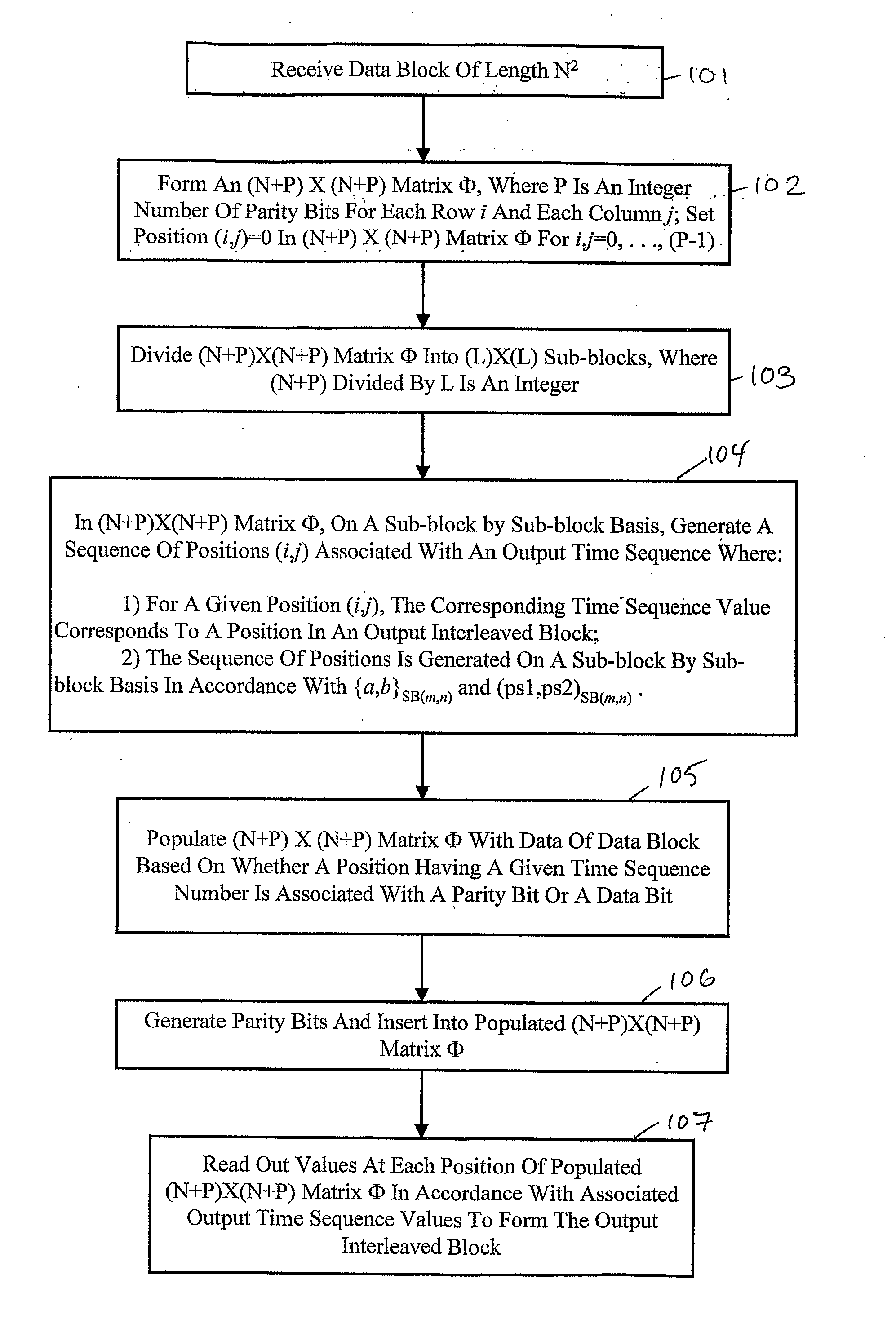
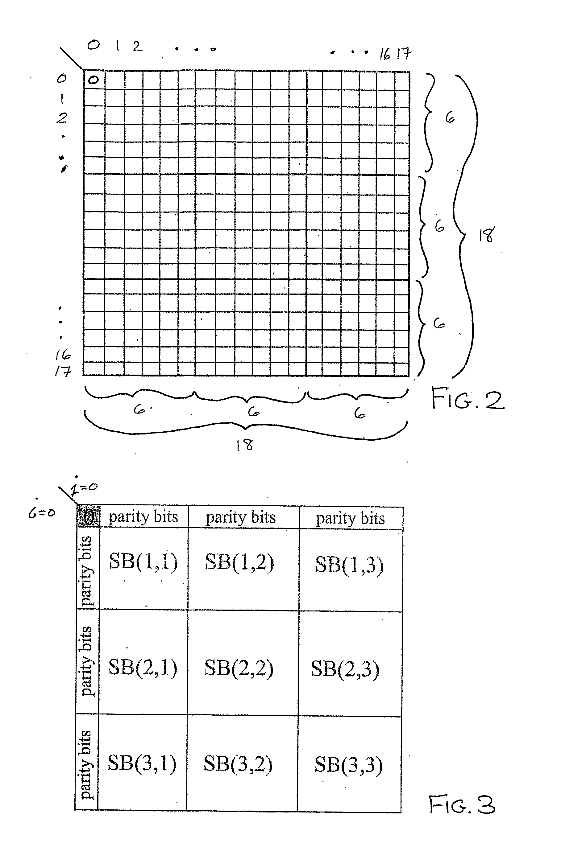
[0027]FIG. 1 shows a method of interleaving in accordance with an exemplary embodiment of the present invention. Method 100 comprises steps 101 through 107. Steps 101 through 104 might be employed by a designed to generate a mapping for an exemplary interleaver implementation, while steps 105 through 107 might be employed by the exemplary interleaver implementation during operation. A given implementation of a de-interleaver operating in accordance with an exemplary embodiment of the present invention might employ a reverse mapping of the corresponding interleaver mapping (called an inverse mapping). An inverse mapping is readily generated given a mapping generated in accordance with an exemplary embodiment of the present invention.

[0028] At step 101, the method receives a block of data (input data block) having a length of NM, where N and M are positive integers greater than 1. For the exemplary embodiment of FIG. 1, N=M=N2 and the method employs two-dimensional matrices. The bloc...


PUM


Abstract

An interleaver employs a generalized method of generating a mapping. The mapping is generated for interleaving bits of a data block and associated error detection/correction information. The data block is of length N, and the length of the error detection/correction information is P. An (N+P)×(N+P) square matrix is formed and divided into sub-blocks, where one portion of the matrix is associated with error detection/correction information and another portion is associated with data of the data block. New positions in the matrix are generated in a time sequence on a sub-block by sub-block basis based on a generator seed pair and an original position seed pair. The time sequence also corresponds to positions in an output interleaved block. Once the new position sequence is generated, the matrix is populated with data and error detection/correction information based on the corresponding time sequence. A de-interleaver performs the inverse mapping of the interleaver.

Description

BACKGROUND OF THE INVENTION [0001] 1. Field of the Invention [0002] The present invention relates to encoding, detection, and decoding of data in communication systems, and, more particularly, to an interleaver and de-interleaver for product code error detection and correction by a receiver. [0003] 2. Description of the Related Art [0004] Many digital transmission systems commonly employ techniques for detection of digital data represented by a sequence of symbols. The symbol bits are transferred as a signal through a transmission (i.e., communication) channel in which noise is typically added to the transmitted signal. For example, magnetic recording systems first encode data into symbol bits that are recorded on a magnetic medium. Writing data to, storing data in, and reading data from the magnetic medium may be considered to take place via a transmission channel that has an associated frequency response. Similarly, wired, optical, wireless, and cellular communication systems also...

Claims


Application Information

Patent Timeline
IPC IPC(8): H03M13/27H03M13/29
CPCH03M13/2703H03M13/2721H03M13/2757H03M13/276H03M13/2918H03M13/2778H03M13/29H03M13/2909H03M13/2764
Inventor LIN, XIAOTONG
Owner BROADCOM INT PTE LTD
Why Eureka
Try Eureka