Autonomous Floor Cleaning Robot

Inactive Publication Date: 2007-11-22
IROBOT CORP
View PDF99 Cites 302 Cited by
  • Summary
  • Abstract
  • Description
  • Claims
  • Application Information

AI Technical Summary

Benefits of technology

[0008] One object of the present invention is to provide a cleaning device that is operable without human intervention to clean designated areas.
[0009] Another object of the present invention is to provide such an autonomous cleaning device that is designed and configured to optimize the cleaning capability and efficiency of its cleaning mechanisms for synergic operations while concomitantly minimizing the power requirements of such mechanisms.
[0010] These and other objects of the present invention are provided by one embodiment autonomous floor-cleaning robot according to the present invention that comprises a housing infrastructure including a chassis, a power subsystem; for providing the energy to power the autonomous floor-cleaning robot, a motive subsystem operative to propel the autonomous floor-cleaning robot for cleaning operations, a control module operative to control the autonomous floor-cleaning robot to effect cleaning operations, and a self-adjusting cleaning head subsyste

Problems solved by technology

One of the primary requirements for an autonomous cleaning device is a self-contained power supply—the utility of an autonomous cleaning device would be severely degraded, if not outright eliminated, if such an autonomous cleaning device utilized a power cord to tap into an external power source.
And, while there have been distinct improvements in the energizing capabilities

Method used


Image

  • Autonomous Floor Cleaning Robot
  • Autonomous Floor Cleaning Robot
  • Autonomous Floor Cleaning Robot

Examples


Embodiment Construction

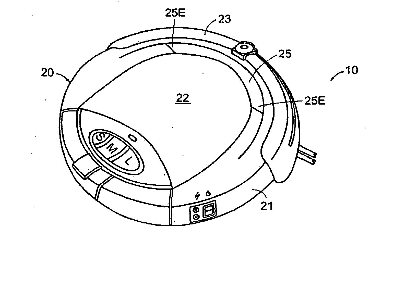
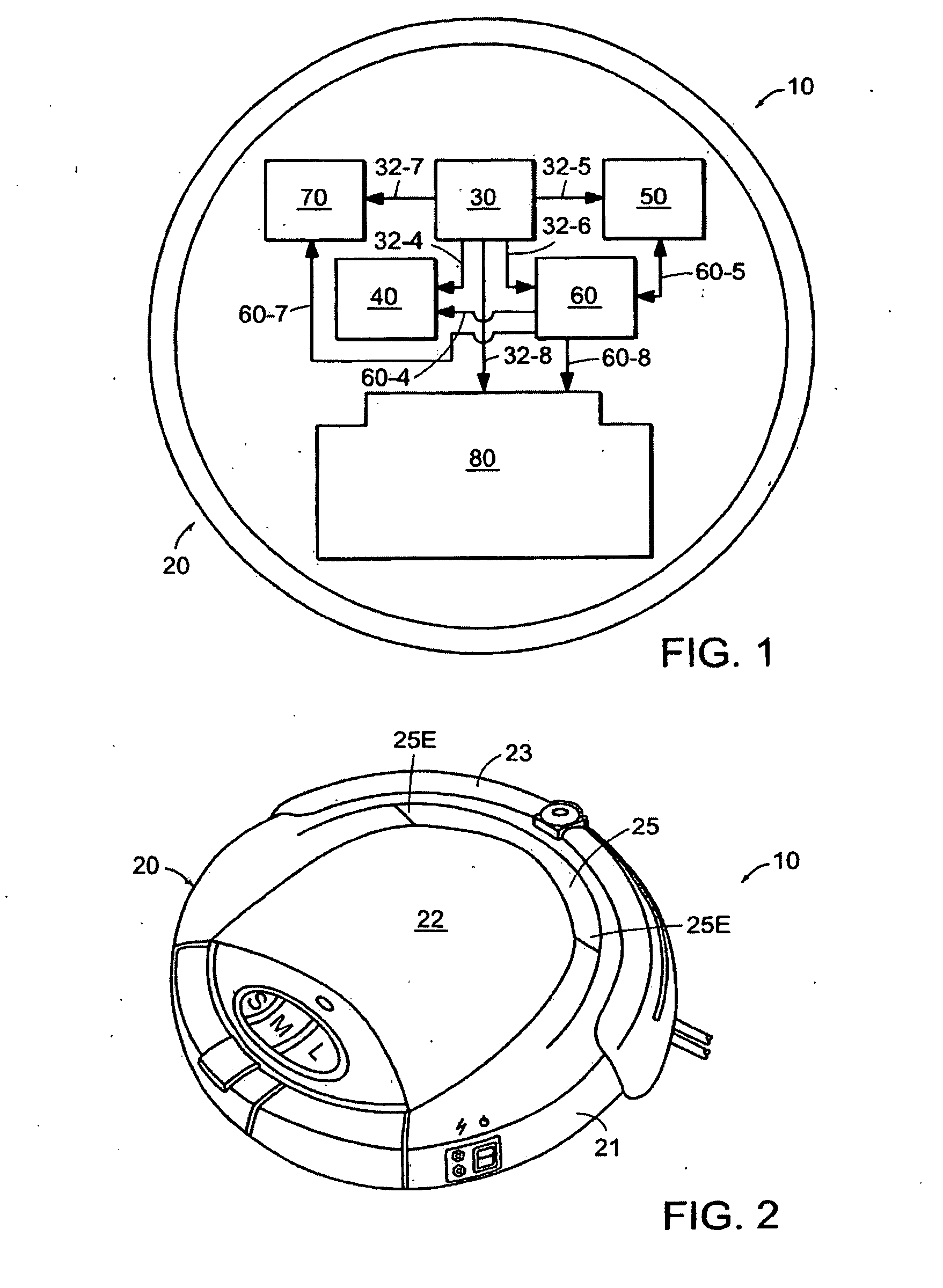
[0026] Referring now to the drawings where like reference numerals identify corresponding or similar elements throughout the several views, FIG. 1 is a schematic representation of an autonomous floor-cleaning robot 10 according to the present invention. The robot 10 comprises a housing infrastructure 20, a power subsystem 30, a motive subsystem 40, a sensor subsystem 50, a control module 60, a side brush assembly 70, and a self-adjusting cleaning head subsystem 80. The power subsystem 30, the motive subsystem 40, the sensor subsystem 50, the control module 60, the side brush assembly 70, and the self-adjusting cleaning head subsystem 80 are integrated in combination with the housing infrastructure 20 of the robot 10 as described in further detail in the following paragraphs.

[0027] In the following description of the autonomous floor-cleaning robot 10, use of the terminology “forward / fore” refers to the primary direction of motion of the autonomous floor-cleaning robot 10, and the t...


PUM


Abstract

An autonomous floor-cleaning robot comprising a housing infrastructure including a chassis, a power subsystem; for providing the energy to power the autonomous floor-cleaning robot, a motive subsystem operative to propel the autonomous floor-cleaning robot for cleaning operations, a command and control subsystem operative to control the autonomous floor-cleaning robot to effect cleaning operations, and a self-adjusting cleaning head subsystem that includes a deck mounted in pivotal combination with the chassis, a brush assembly mounted in combination with the deck and powered by the motive subsystem to sweep up particulates during cleaning operations, a vacuum assembly disposed in combination with the deck and powered by the motive subsystem to ingest particulates during cleaning operations, and a deck adjusting subassembly mounted in combination with the motive subsystem for the brush assembly, the deck, and the chassis that is automatically operative in response to an increase in brush torque in said brush assembly to pivot the deck with respect to said chassis. The autonomous floor-cleaning robot also includes a side brush assembly mounted in combination with the chassis and powered by the motive subsystem to entrain particulates outside the periphery of the housing infrastructure and to direct such particulates towards the self-adjusting cleaning head subsystem.

Description

CROSS-REFERENCE TO RELATED APPLICATIONS [0001] The subject matter of this application claims priority from U.S. Provisional Application Ser. No. 60 / 345,764 filed 03 Jan. 2002, entitled CLEANING MECHANISMS FOR AUTONOMOUS ROBOT. The subject matter of this application is also related to commonly-owned, co-pending U.S. patent application Ser. No. 09 / 768,773, filed 24 Jan. 2001, entitled ROBOT OBSTACLE DETECTION SYSTEM; Ser. No. 10 / 167,851, filed 12 Jun. 2002, entitled METHOD AND SYSTEM FOR ROBOT LOCALIZATION AND CONFINEMENT; and, Ser. No. 10 / 056,804, filed 24 Jan. 2002, entitled METHOD AND SYSTEM FOR MULTI-MODE COVERAGE FOR AN AUTONOMOUS ROBOT.BACKGROUND OF THE INVENTION [0002] (1) Field of the Invention [0003] The present invention relates to cleaning devices, and more particularly, to an autonomous floor-cleaning robot that comprises a self-adjustable cleaning head subsystem that includes a dual-stage brush assembly having counter-rotating, asymmetric brushes and an adjacent, but inde...

Claims


Application Information

Patent Timeline
IPC IPC(8): A47L11/24A47L5/30A47L5/34A47L9/00A47L9/04
CPCA47L5/30A47L5/34A47L7/02A47L9/009A47L9/0411A47L2201/04A47L2201/06A47L11/282A47L11/4061A47L11/4066A47L2201/00A47L9/0477A47L9/0494A47L9/1409A47L9/2826A47L9/2852A47L9/2894A47L9/32
Inventor JONES, JOSEPH L.MACK, NEWTON E.NUGENT, DAVID M.SANDIN, PAUL E.
Owner IROBOT CORP
Why Eureka
Try Eureka