Spiral rope for liana raising, manufacturing method for the spiral rope and wall surface greening system

a manufacturing method and spiral rope technology, applied in the field of spiral rope for liana raising, can solve the problems of deterioration of appearance, difficulty in smoothly winding the liana around the rope, and possible separation from the rop

Inactive Publication Date: 2007-11-22
ASAHI INTECC CO LTD
View PDF4 Cites 11 Cited by
  • Summary
  • Abstract
  • Description
  • Claims
  • Application Information

AI Technical Summary

Benefits of technology

[0034]To achieve the above mentioned object of the present invention, there is provided a manufacturing method for a spiral rope for liana raising which comprises the steps of:
[0035]forming a core coating layer and a side coating layer with an identical or same kind of resin material so as to coat a core member and a side member respectively formed from austenite-based stainless steel twisted wires; and
[0036]winding the side member around the core member spirally at intervals in a direction along a winding direction of a twiner of a liana,
[0037]wherein at least one of said core coating layer

Problems solved by technology

Therefore, in applying the wire stretching device to a liana, there arises a drawback that a twiner of the liana is hard to smoothly wind around the rope and may be detached from the rope, if the above-mentioned steel wires is wound around the wire main body toward a direction which

Method used


Image

  • Spiral rope for liana raising, manufacturing method for the spiral rope and wall surface greening system
  • Spiral rope for liana raising, manufacturing method for the spiral rope and wall surface greening system
  • Spiral rope for liana raising, manufacturing method for the spiral rope and wall surface greening system

Examples


first embodiment

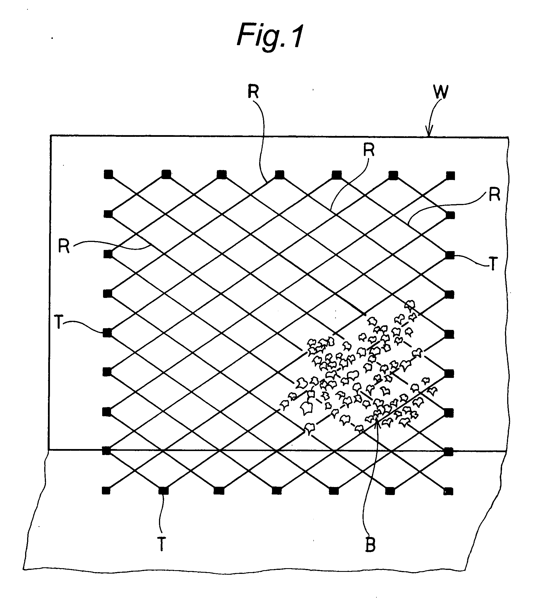
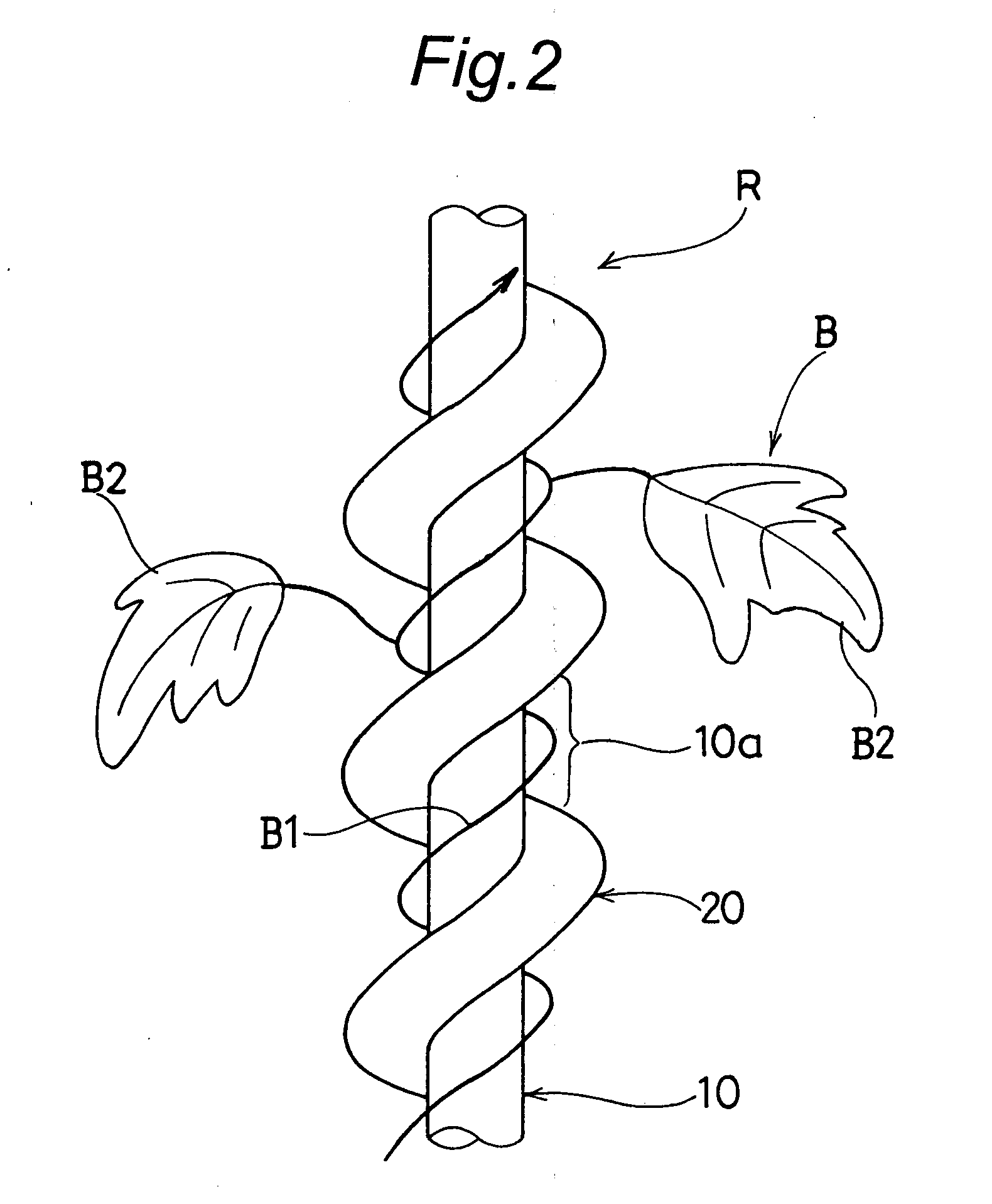
[0062]These spiral ropes Rare, as shown in FIG. 1, supported by a plurality of tightening metallic fittings T between an upper portion of a wall surface W and the ground in such a manner that they are opposed to the wall surface W in an inclined state against the wall surface W with a diamond cross pattern, which is one of predetermined stretching patterns. In the first embodiment, a liana B is, in FIGS. 1 and 2, shown as an example which grows along the wall surface greening system.

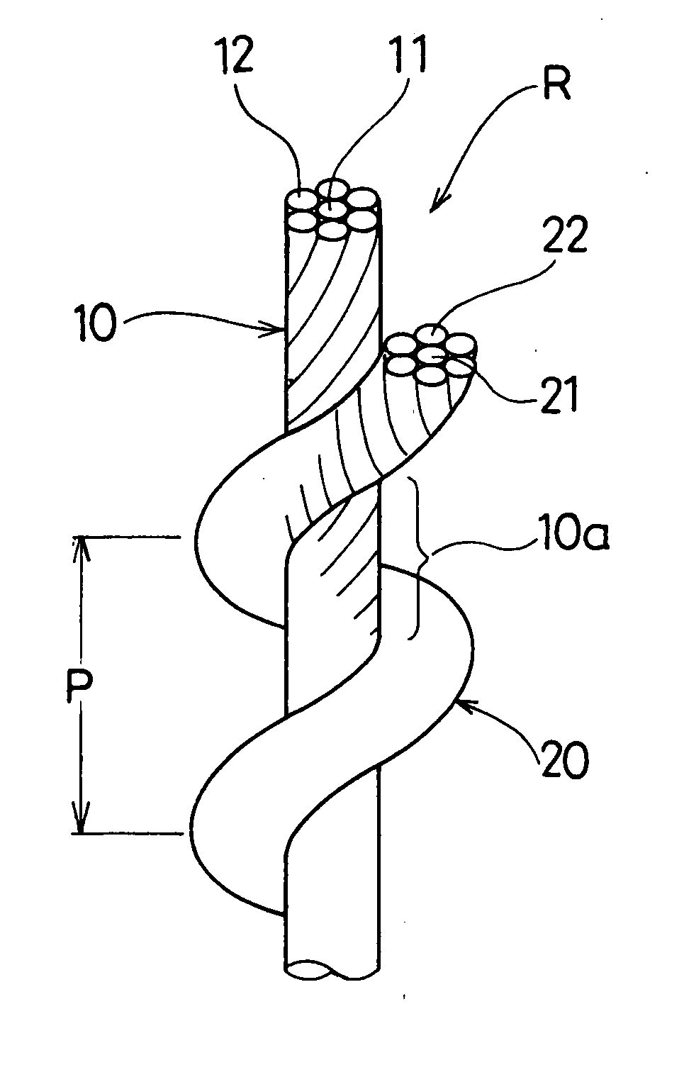
[0063]The spiral rope R has, as shown in FIGS. 2 and 3, a core member 10 and a side member 20. The core member 10 is formed as a twisted wire including one core element wire 11 around which 6 or six side element wires 12 are twisted in Z-like shape (see FIG. 3).

[0064]The side member 20 is formed as a twisted wire including one core element wire 21 around which 6 or six side element wires 22 are twisted into a S-like shape. The side member 20 is spirally wound around the core member 10 along the longitudi...

second embodiment

[0102]In the second embodiment, in the core rope member Ra, the outer diameter of the core strand is 0.77 mm, and the outer diameter of the element wire consisting of the core of the core strand 30 is 0.27 mm. The outer diameter of the element wire of the side strand consisting of the side portions of the core strand 30 is 0.25 mm, and the outer diameter of the side strand 40 is 0.66 mm. Further, the outer diameter of the element wire consisting of the core of the side strand 40 is 0.22 mm and the outer diameter of the element wire of the side strand consisting of the side portions of the side strand 40 is 0.22 mm.

[0103]As shown in FIG. 10, the side rope member Rb is constructed as a twisted wire in which six side element wires 52 are twisted around one core element wire 51 at a twisting pitch of 6.40 mm in the form of the Z-like shape. In this embodiment, the core element wire 51 and the respective side element wires 52 are made of the austenite-based stainless steel wires describe...

third embodiment

[0119]In the third embodiment as constructed above, in the spiral rope R2, four bundles of the side strands 20A are, as described above, wound around the core strand 10A in the counter-clockwise direction (in the twisting direction in the form of the Z-like shape) in such a manner that they extend along the winding direction (counter-clockwise direction) of the twiner B1 of the liana B which grows in the Northern Hemisphere of the earth. Furthermore, the spiral grooves 10c are formed around the outer periphery of the core strand 10A as described above (see FIG. 11).

[0120]Therefore, the liana B grows, as same as the first embodiment, in such a manner that the twiner B1 winds smoothly around the core strand 10A in the clockwise direction along the spiral grooves 10c. As a result, the same effects as those of the first embodiment can be also achieved in this third embodiment.

[0121]Further, as described above, the spiral rope R2 has the structure with two bundles of side strands lacked....


PUM


Abstract

A spiral rope R for liana raising includes a core member 10 and a side member 20. The side member 20 is wound around the core member 10 in the winding direction of a twiner B1 of a liana B which grows up in the Northern Hemisphere of the earth.

Description

BACKGROUND OF THE INVENTION[0001]1. Field of the Invention[0002]The present invention relates to a spiral rope for liana raising, a manufacturing method for the spiral rope and a wall surface greening system using the spiral rope.[0003]2. Description of the Related Art[0004]As a spiral rope of this kind, there is, conventionally, a rope adopted in a wall surface greening technology and a wire stretching device disclosed in Japanese Laid-Open Patent Publication No. 2006-36. This rope is constructed as follows.[0005]A wire member which is formed by a metallic core member with a resin coated is spirally wound around a wire main body which is formed with steel wires twisted up together and is coated with a resin.[0006]However, the rope adopted in the wall surface greening technology and the wire stretching device as described above has merely the above-mentioned spirally wound construction.[0007]Therefore, in applying the wire stretching device to a liana, there arises a drawback that a...

Claims


Application Information

Patent Timeline
IPC IPC(8): D02G3/36
CPCA01G9/12D07B1/0673D07B1/14D07B5/005D07B2205/3032D07B2801/10
Inventor KATO, TOMIHISAHOSHIYA, TAKAO
Owner ASAHI INTECC CO LTD
Why Eureka
Try Eureka