Cutting device, finisher and bookbinding system provided therewith

a finishing device and finishing technology, applied in the direction of electrographic process, transportation and packaging, instruments, etc., can solve the problems of affecting the operation of the apparatus, the failure of the suspension or the failure of the sheet bundle, and the inability to remove the minute chips attached to the cutting blad

Active Publication Date: 2007-11-22
KONICA MINOLTA BUSINESS TECH INC
View PDF1 Cites 21 Cited by
  • Summary
  • Abstract
  • Description
  • Claims
  • Application Information

AI Technical Summary

Benefits of technology

[0013]An object of the cutting device of the present invention is to avoid a possible apparatus operation failure or suspension, or conveyance failure of the sheet bundle SS, by ensuring that the chips generated by the cutting device will not remain in the vicinity of the cutting blade, not deposit on various members of the cutting device or not enter the apparatus.

Problems solved by technology

In this arrangement, minute chips attached to the cutting blade cannot be removed through direct contact with the cutting blade.
However, even if it is possible to remove the large-sized chips that can be brought into contact with the paddles, small-sized chips are not brought into contact with the paddles.
The chips having been cut slip down the chip falling cover extending continuously to the blade surface of the cutter tip, and the chips depositing on the cutter tip cannot be removed.
This will cause apparatus operation failure or suspension or conveyance failure of the sheet bundle SS.

Method used


Image

  • Cutting device, finisher and bookbinding system provided therewith
  • Cutting device, finisher and bookbinding system provided therewith
  • Cutting device, finisher and bookbinding system provided therewith

Examples


Embodiment Construction

[0031]The present invention is detailed with reference to embodiments given in the drawings as follows.

[Cutting device]

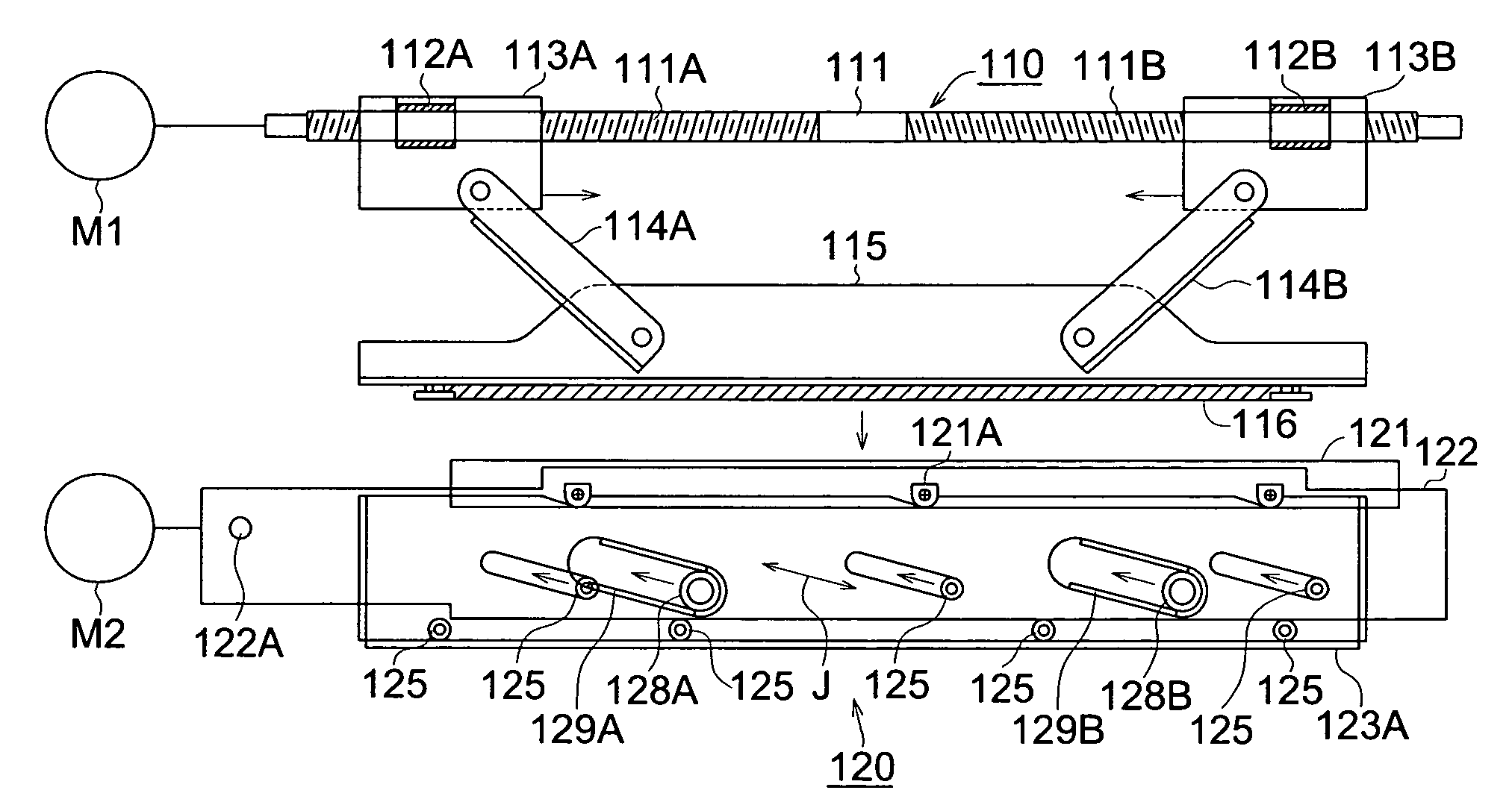
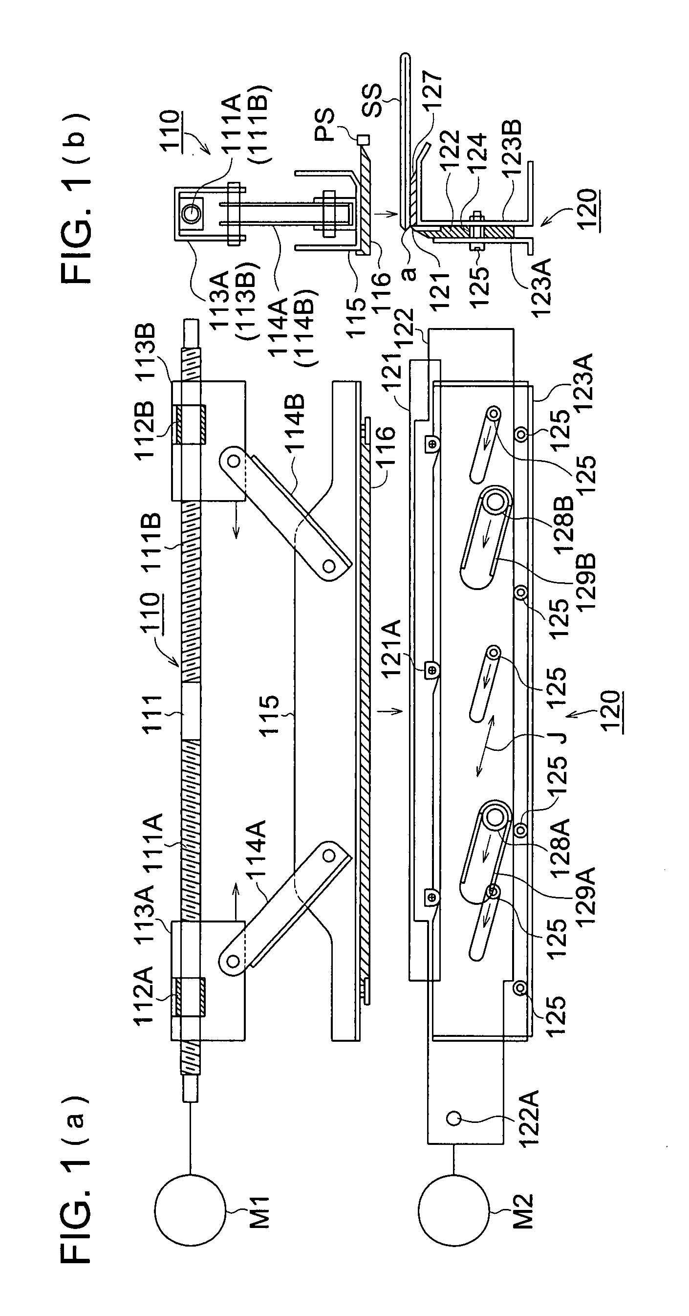
[0032]FIG. 1(a) is a front view of the major sections representing the standby state of a cutting device 100. FIG. 1(b) is a side view of the major sections thereof.

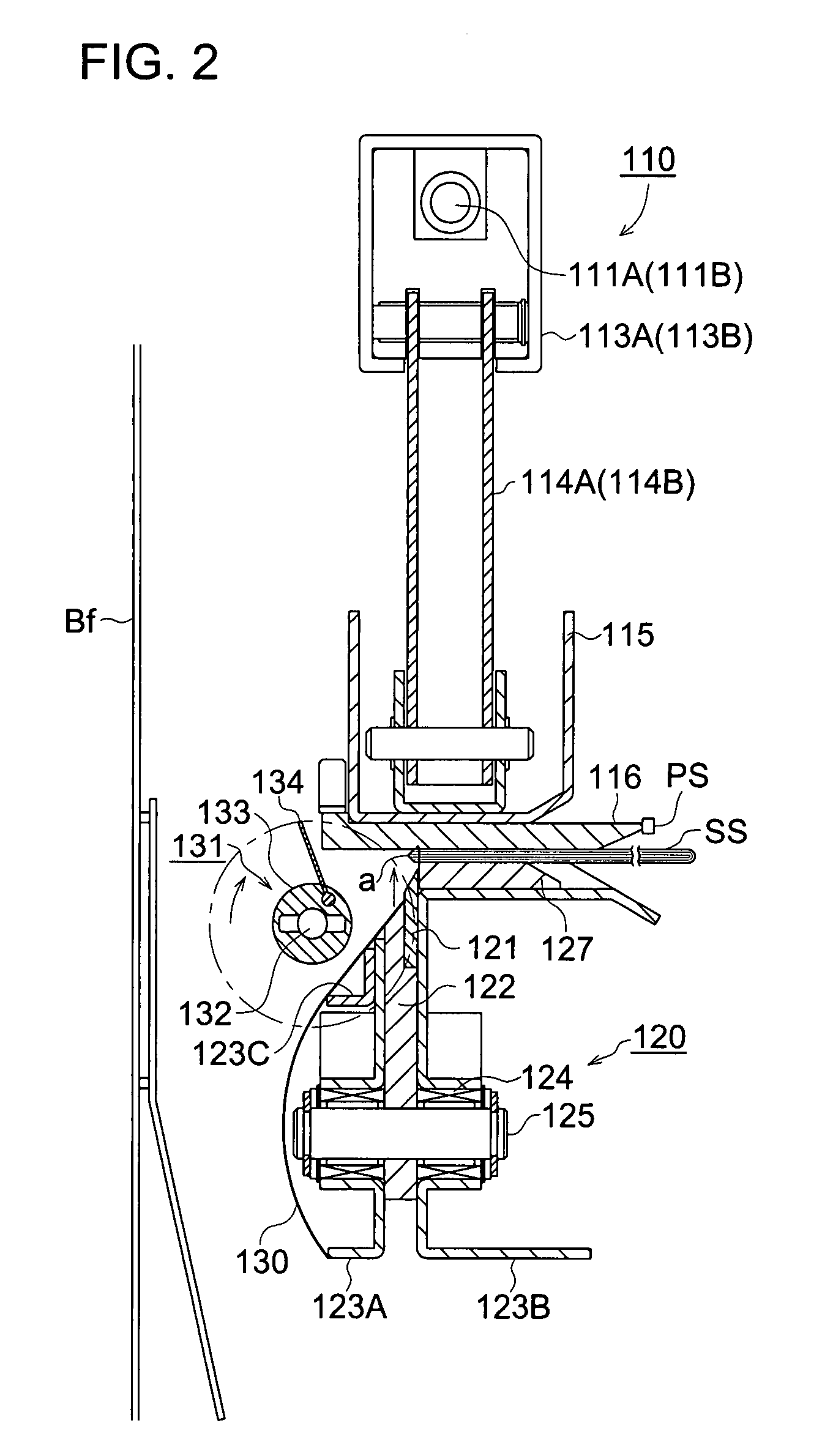
[0033]A blade receiving section 110 is arranged on the upper part of the main body of the cutting device 100, and a cutting blade section 120 is mounted on the lower part of the main body.

[0034]The edge portion “a” as a tip part of the sheet bundle SS conveyed to the cutting device 100 is cut by the lowering of the blade receiving plate 116 of the blade receiving section 110 in the vertical direction, and the subsequent rising of the cutting blade 121 of the cutting blade section 120 in the oblique direction.

[0035]A rotary shaft 111 with the both ends supported is mounted on the upper part of the blade receiving section 110. The rotary shaft 111 is driven by a motor M1. The rotary shaft 111 is provided w...


PUM

PropertyMeasurementUnit
thicknessaaaaaaaaaa
thicknessaaaaaaaaaa
lengthaaaaaaaaaa

Abstract

A cutting device that cuts an edge portion of a sheet bundle having plural sheets stacked, includes: a cutting blade; a paddle provided on a side of the cutting blade, which removes chips attached to the cutting blade by rubbing a side surface of the cutting blade; a controller which controls drive of the paddle. The controller includes a judging section which compares a length of the chips in a direction perpendicular to an edge side of the sheet bundle to be cut by the cutting blade with a predetermined length that has been preset. When the length of the chips is shorter than the predetermined length, the controller makes the paddle to rotate in a predetermined direction, and when the length of the chips is longer than the predetermined length, the controller makes the paddle to rotate in a reverse direction.

Description

[0001]This application is based on Japanese Patent Application Nos. 2006-138695 filed on May 18, 2006 and 2006-351498 filed on Dec. 27, 2006, which are hereby incorporated by reference.BACKGROUND OF THE INVENTION[0002]The present invention relates to a cutting device for cutting the edge portion of a sheet bundle in which a plurality of sheets are stacked on top of one another, a finisher for finishing the sheet ejected from the image forming apparatus, on which an image has been formed, thereby creating a sheet bundle and cutting the edge portion of the sheet bundle, and a bookbinding system equipped with an image forming apparatus and the aforementioned finisher.[0003]Heretofore, there has been provided a finisher equipped with a cutting device, that receives sheets on which images have been formed by an image forming apparatus such as a photocopier and printer, and binds the sheets by performing the processes of center-binding and center-folding, and then cuts and trims the edge ...

Claims


Application Information

Patent Timeline
Patent Type & Authority Applications(United States)
IPC IPC(8): B65H39/10B26D5/28
CPCB26D1/08B26D1/085B26D7/025B26D7/1818B42C1/12G03G2215/00814B65H35/06B65H2301/543B65H2801/09G03G15/6582B42C5/00Y10T83/4465
Inventor WAKABAYASHI, HIROYUKIUCHIYAMA, MASAAKISHIOKAWA, TSUYOSHI
Owner KONICA MINOLTA BUSINESS TECH INC
Why Eureka
Try Eureka