Flash discharge lamp

Active Publication Date: 2007-11-22
USHIO DENKI KK
View PDF1 Cites 5 Cited by
  • Summary
  • Abstract
  • Description
  • Claims
  • Application Information

AI Technical Summary

Benefits of technology

[0019]The invention was devised to eliminate the above described disadvantages in the prior art. Therefore, a primary object of the present invention is to devise a flash discharge lamp in which the flash discharge lamp can supply enough trigger energy and reliable emission can take place.
[0028]This means that the disadvantage of tearing of the metal foil and similar disadvantages are thus eliminated. As a result, reliable emission of the lamp can take place.
[0029]Furthermore, by forming a coating layer of metal with a high melting point on the surface of the recessed part of the trigger electrode, the trigger electrode can be prevented from adhering to the sealed tubular body because an oxide with a high affinity to the material comprising the sealed tubular body is not formed on the surface of the recessed part. As a result, crack formation in the sealed tubular body can be prevented.
[0030]Additionally, it is desired that the concave part of the trigger electrode be placed behind the tip position of the corresponding electrode within the arc tube. The reason for this is that, even if the vicinity of the metal foil of the trigger electrode is not irradiated with the radiant light of the lamp, or even if it is irradiated therewith, there is hardly any effect on the expansion and contraction of the trigger electrode since the light output is reduced. As a result destruction of the metal foil can be prevented.

Problems solved by technology

Furthermore, when light is emitted from the lamp in the space in the vicinity of the lamp, shock waves are formed.
Thus, there is the disadvantage that the operating property of the lamp becomes extremely unstable.

Method used


Image

  • Flash  discharge lamp
  • Flash  discharge lamp
  • Flash  discharge lamp

Examples


Embodiment Construction

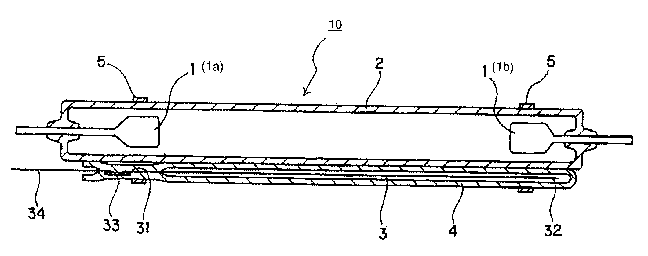
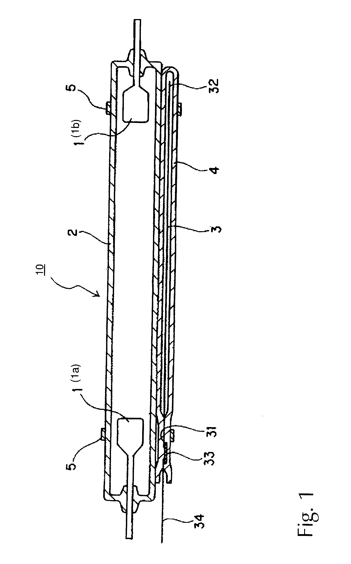
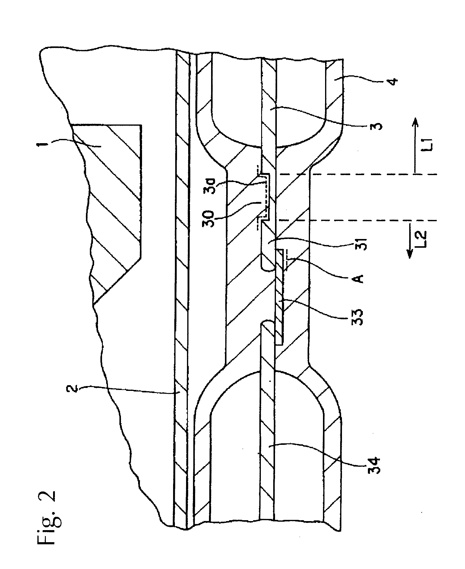
[0040]The overall arrangement of the flash discharge lamp 10 in accordance with the invention is shown in FIG. 1. FIG. 2 shows an enlarged view of the region with the sealed arrangement of the sealed tubular body 4.

[0041]The lamp 10 comprises an arc tube 2, a trigger electrode 3 and a sealed tubular body 4. The arc tube 2 is formed, for example, of silica glass and is tubular. Within the arc tube 2, there is a pair of opposed electrodes 1 (1a, 1b). The trigger electrode 3 extends in the lengthwise direction of the arc tube 2 on the outside of the arc tube 2. The trigger electrode 3 is arranged such that it is jacketed by the sealed tubular body 4.

[0042]The arc tube 2 is, for example, filled with xenon gas. Its two ends are sealed. A discharge space is formed within the arc tube 2. The electrodes 1 (1a, 1b), in the case of operation using an alternating current, as is shown in the drawings, have the same shape and the same size. However, in the case of operation using a direct curren...


PUM


Abstract

Flash discharge lamp having an arc tube in which there is a pair of opposed electrodes, a rod-shaped trigger electrode which runs along the outside surface of the arc tube in its lengthwise direction; and a sealed tubular body which jackets the trigger electrode and has a hermetically sealed arrangement containing a metal foil. The trigger electrode has a recessed part on its surface in the vicinity of the metal foil and the recessed part is at least partially filled with the material of which the sealed tubular body is formed.

Description

BACKGROUND OF THE INVENTION[0001]1. Field of the Invention[0002]The invention relates to a flash discharge lamp which is used, for example, for heat treatment of semiconductor substrates and liquid crystal substrates and for similar purposes. The invention relates especially to a flash discharge lamp in which the outside surface of the arc tube is provided with a trigger electrode.[0003]2. Description of Related Art[0004]Conventionally, a flash discharge lamp is common in which the outside of the arc tube in which a pair of opposed electrodes is arranged is provided with a trigger electrode.[0005]Furthermore, a lamp is known in which, within a sealed tubular body of silica glass, a trigger electrode is sealed and in which this sealed tubular body is located along the arc tube of the flash discharge lamp (hereinafter also called “lamp”).[0006]This technology is described in Japanese Patent Application JP-A-2003-203606 and corresponding U.S. Pat. No. 6,960,883.[0007]A conventional fla...

Claims


Application Information

Patent Timeline
IPC IPC(8): H01J17/00
CPCH01J61/547H01J61/90H01J61/80
Inventor FUSE, TETSUOSHOJO, KATSUMIHIRAISHI, TAKAYUKI
Owner USHIO DENKI KK
Why Eureka
Try Eureka