Miniature surface-mount electronic component and method for manufacturing the same

Active Publication Date: 2007-11-22
MURATA MFG CO LTD
View PDF4 Cites 1 Cited by
  • Summary
  • Abstract
  • Description
  • Claims
  • Application Information

AI Technical Summary

Benefits of technology

[0029] As described above, according to the present invention, by providing the vertical grooves on both side surfaces facing in opposite directions of the flanges of the bar-shaped core, and molding the outer casing with the projections (pins) for fixing raised in the mold for molding the outer casing, positional displacement occurring when the outer casing is molded can be prevented. In the metal plate terminals, by fixing the metal plate to the base made of the insulating resin, and fitting and fixing a pair of pillar portions provid

Problems solved by technology

However, the core is a brittle sintered body, and is originally weak against impact and vibrations as earthenware.
In addition, for the above described reason, the core tends to be weak against impact and vibrations, and cannot help being formed into a slim and long shape.
However, in these coils, core breakage due to the terminal holding structure of the core b

Method used


Image

  • Miniature surface-mount electronic component and method for manufacturing the same
  • Miniature surface-mount electronic component and method for manufacturing the same
  • Miniature surface-mount electronic component and method for manufacturing the same

Examples


Embodiment Construction

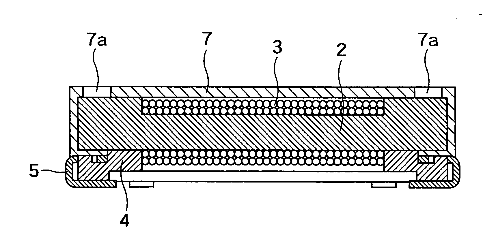
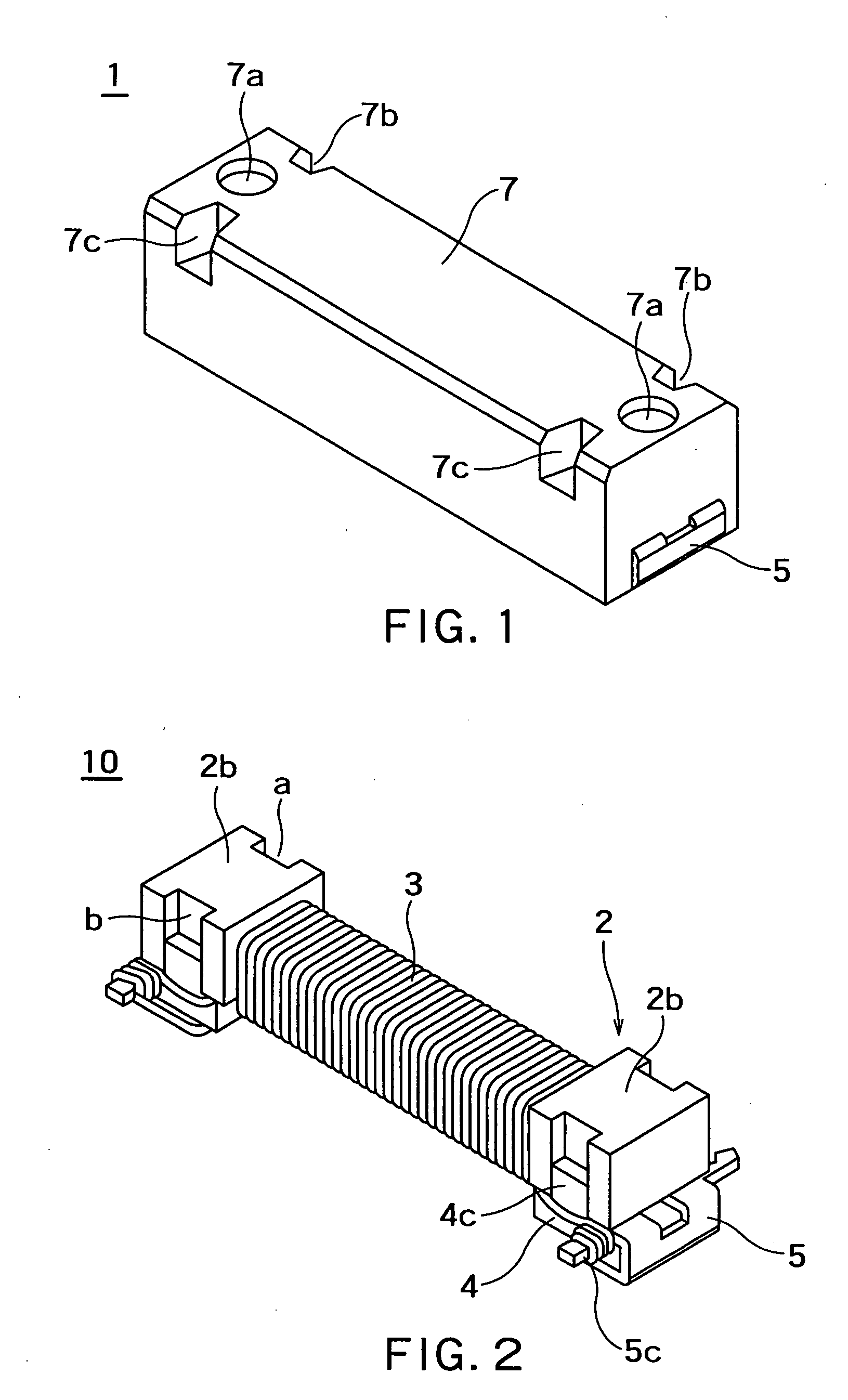
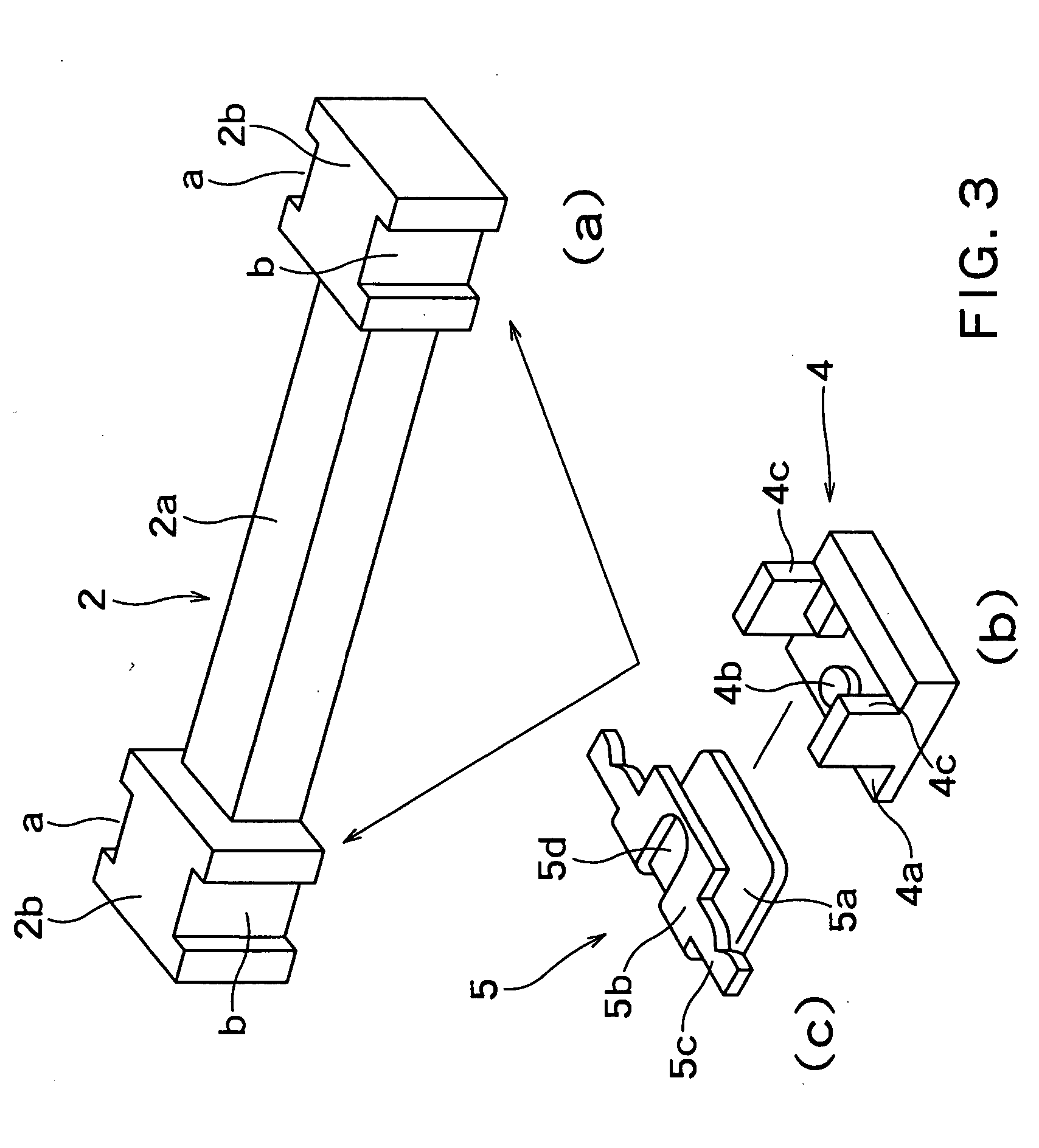
[0036]FIG. 1 is an external perspective view showing one embodiment of a miniature surface-mount electronic component according to the present invention. FIG. 2 is a perspective view of a coil which is an internal configuration of the miniature surface-mount electronic component shown in FIG. 1, and FIGS. 3(a) to 3(c) are exploded perspective views of a core and a terminal which is the internal configuration of the miniature surface-mount electronic component shown in FIGS. 1 and 2. FIG. 4 shows a front sectional view of the miniature surface-mount electronic component. The miniature surface-mount electronic component is applied to an antenna, a vehicle-mounted antenna, a transponder, a choke coil, an inductor of an electronic device and the like.

[0037] As shown in FIGS. 1 to 4, a miniature surface-mount electronic component 1 includes a core 2 in the shape of a bar long in a longitudinal direction, a winding wire 3, a base 4, a metal plate 5 and an outer casing 7 made of an insula...


PUM

PropertyMeasurementUnit
Electrical resistanceaaaaaaaaaa
Impact resistanceaaaaaaaaaa

Abstract

A miniature surface-mount electronic component which can ensure sufficient impact resistance and vibration resistance especially in an application to a severe use environment such as a vehicle-mounted coil, by putting some contrivance into a method for fixing a coil in a molding process and a method for holding a core and terminals. A miniature surface-mount electronic component including a bar-shaped core 2 on which a winding wire 3 is wound, and metal plates 5, with an outer casing 7 made of an insulating resin molded, includes flanges 2b substantially quadrangular in section at both ends of the bar-shaped core 2, and vertical grooves a and b are provided on side surfaces of the flanges 2b of the bar-shaped core 2 as fixing portions for preventing positional displacement occurring when the outer casing 7 is molded.

Description

CROSS REFERENCE TO RELATED APPLICATIONS [0001] This application is based upon and claims the benefit of priority from the prior Japanese Patent Application No. 2006-140193, filed on May 19, 2006, the entire contents of which are incorporated herein by reference. BACKGROUND OF THE INVENTION [0002] 1. Field of the Invention [0003] The present invention relates to a miniature surface-mount electronic component in which a coil wound on a ferrite core is resin-molded. A miniature surface-mount electronic component according to the present invention includes an antenna applicable to a vehicle-mounted transponder or the like, an inductor for a communication device, a choke coil or the like. [0004] 2. Related Art [0005] Various types of miniature surface-mount electronic components have been conventionally proposed, and have been in practical use. As one of them, a miniature surface-mount electronic component applicable as a vehicle-mounted antenna or a transponder has been proposed recentl...

Claims


Application Information

Patent Timeline
IPC IPC(8): H01F27/02
CPCH01F17/045H01F27/022H01F27/027H01F27/292H01F41/10Y10T29/4913Y10T29/49174Y10T29/49073Y10T29/4922Y10T29/49005Y10T29/49071Y10T29/4908Y10T29/49147
Inventor YAGI, MASAYOSHISHIMIZU, SHINGOMURAKAMI, SHIN
Owner MURATA MFG CO LTD
Why Eureka
Try Eureka