Bi-Directional Radio Monitoring System

a radio monitoring and bi-directional technology, applied in the field of radio monitoring systems, can solve the problems of long delay, inability to recognise and identify the correct individual identification signal, and inability to achieve the effect of reducing unnecessary power consumption, reducing the frequency of access devices polling transmissions, and eliminating reception nulls

Inactive Publication Date: 2007-11-22
AUSTRALIAN ARROW
View PDF5 Cites 82 Cited by
  • Summary
  • Abstract
  • Description
  • Claims
  • Application Information

AI Technical Summary

Benefits of technology

[0035] Lower power communication protocols may also be developed to prevent the base controller attempting to track the access device constantly, with the aim of reducing unnecessary power consumption. Thus, if the access device is left within proximity of the vehicle for a predetermined period, without moving, the system may enter a stand-by mode. Other strategies may involve the use of movement sensors and/or activity profiles. A movement sensor can detect if the access device is moving, or has moved within a predetermined period, to determine its polling period. Thus, if a movement sensor indicates no movement for a predetermined time, the polling period may be increased to ten or twenty seconds or more. As soon as a movement sensor indicates movement, the polling period may be decreased to the normal preset period. Similarly, an activity profile can reduce the frequency of the access device polling transmissions during periods where the access device has historically had less usage. This may be during certain periods during the day, such as at night-time, or some other profile may

Problems solved by technology

Such signals may be received in a manner to interfere with each other so that, consequently, the base station may be unable to recognise and identify a correct individual identifying signal.
However, when multiple transponders, such as those associated with a car pool, are in use, long delays may then be experienced before access to the vehicle is authorised.
Such delays are undesirable in

Method used


Image

  • Bi-Directional Radio Monitoring System
  • Bi-Directional Radio Monitoring System
  • Bi-Directional Radio Monitoring System

Examples


Embodiment Construction

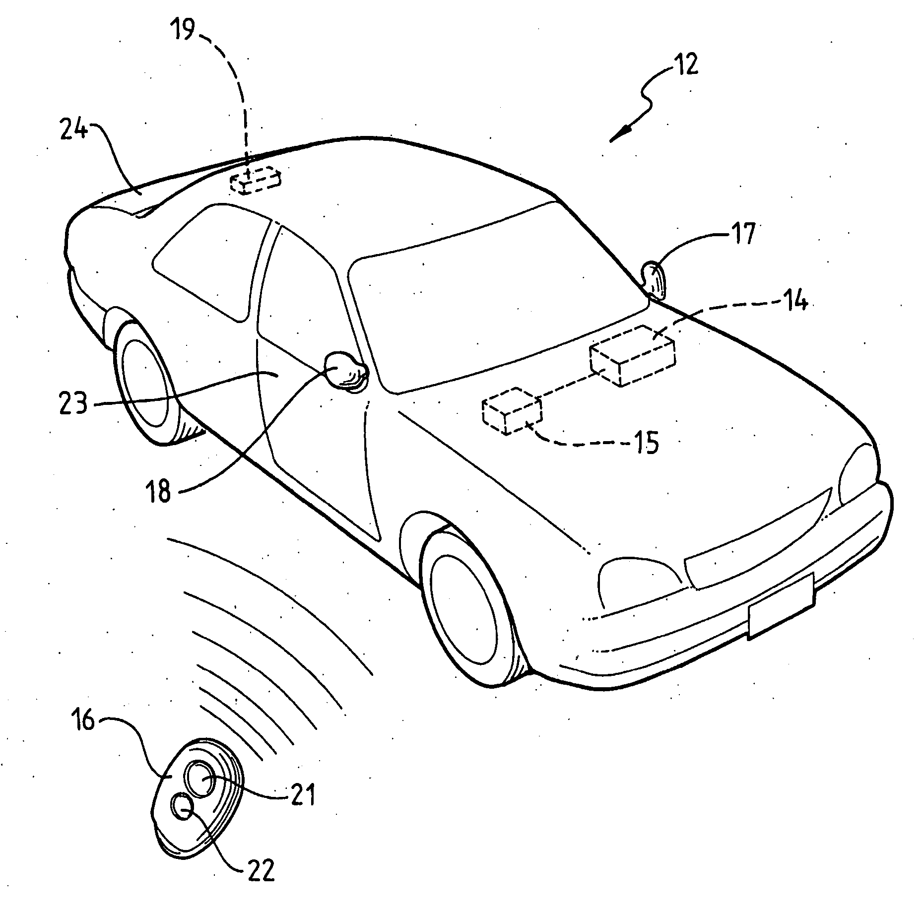
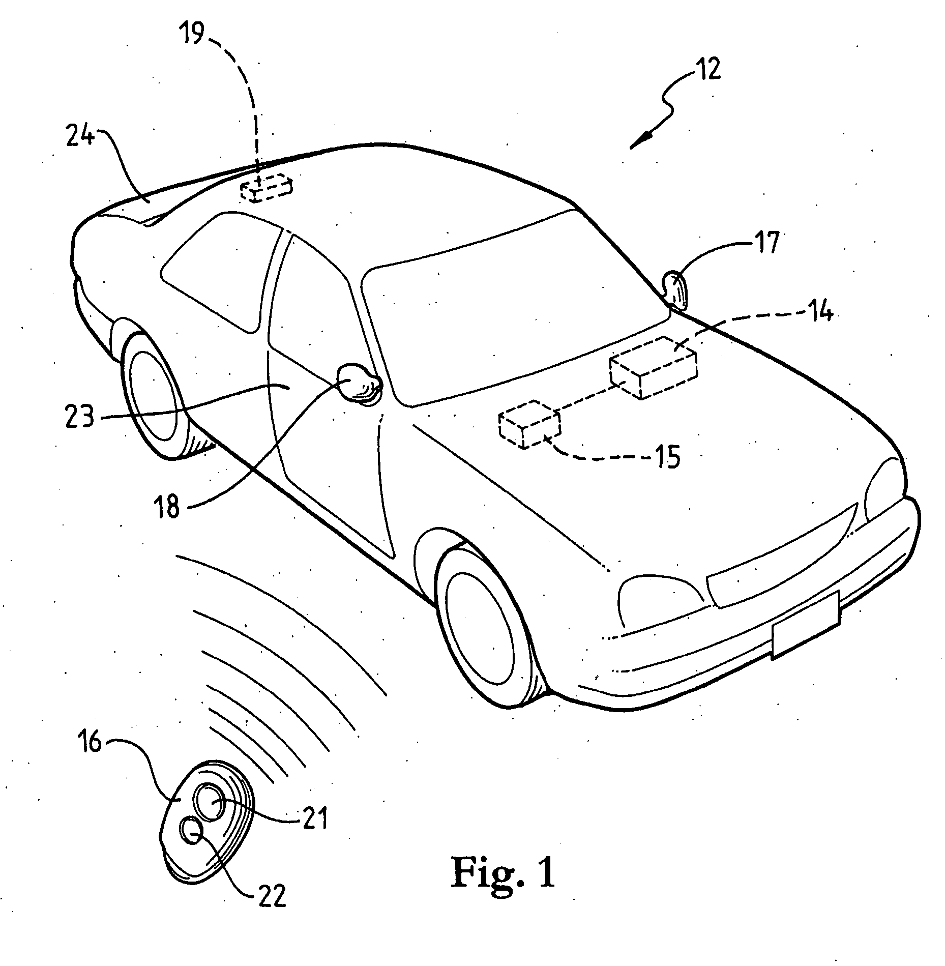
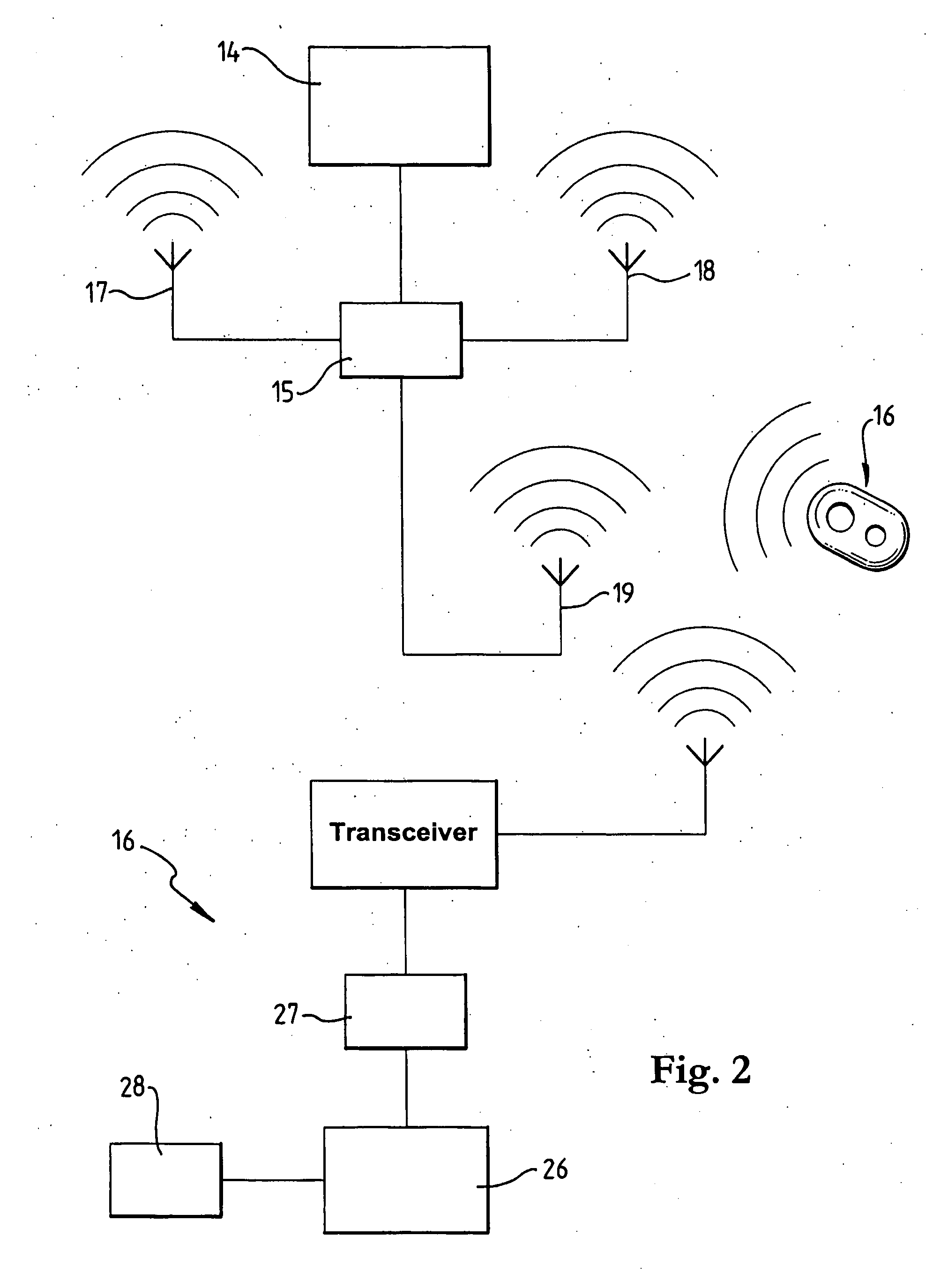
[0044] Referring to FIGS. 1 and 2 , this embodiment of the invention will be described with reference to its use in relation to a motor vehicle 12. The vehicle has a base controller 14 which controls a high date rate, bidirectional wireless transmitter / receiver (transceiver) 15, which provides RF communications with one or more portable access devices 16. The portable access devices 16 each incorporate a transceiver, and they are also provided, in this preferred embodiment, with pushbuttons 21 and 22 which, on actuation, initiate RF signal generation which, on authentication, cause the base controller to lock or unlock a vehicle door 23 or boot (trunk) lid 24, in a known manner. Thus, the portable access device 16 enables remote keyless entry and locking of the vehicle 12.

[0045] The transceiver 15 in the vehicle 12 communicates with the transceiver in the access device 16 through at least two, and preferably three antennae which form fixed references. One antenna is located in the ...


PUM


Abstract

A bi-directional radio monitoring system includes a base unit (14) having a base RF transceiver (15) with two or more fixed antennae (17, 18, 19) associated therewith. The base unit communicates with a portable transceiver (16) using ultra high frequency (UHF) radio signals whereby, by using the two or more antennae (17, 18, 19), the base unit (14) is able to determine a relative position of the portable transceiver (16), depending on the closeness of the movable transceiver (16) to each of the fixed transceiver antennae (17, 18, 19). The RF signal transmission by the base unit (14) may vary in terms of channel, power, packet length, data rate and packet contents transmitted from each antennae (17, 18, 19) to give rise to responses from the portable transceiver (16) that enable the base unit (14) to track the movement of the portable transceiver (16).

Description

FIELD OF THE INVENTION [0001] This invention relates to a radio monitoring system for equipment or equipment functions and relates particularly to a short range monitoring system that uses bi-directional radio communications in a variety of functional applications. The invention is particularly suitable for use in a passive access system to allow authorised access to a restricted area. BACKGROUND OF THE INVENTION [0002] While the invention has broad application, it will be described with particular reference to a passive access system which uses an electronic access device, preferably a portable device, that communicates with a base controller to negotiate access to the restricted area., such as access or entry to a motor vehicle, building, room, container or the like. It will be understood, however, that the broader applications of the invention include monitoring equipment such as that associated with a motor vehicle, for example, tyre pressure monitoring, equipment status monitor...

Claims


Application Information

Patent Timeline
IPC IPC(8): B60R25/10G06F7/04H04W64/00
CPCB60R25/2072B60R25/24G07C2209/63G07C2009/00793G07C9/00309
Inventor LITTLE, ANTHONY RUSSELL
Owner AUSTRALIAN ARROW
Why Eureka
Try Eureka