Liquid crystal display and method for driving the same

a technology of liquid crystal display and liquid crystal cell, which is applied in the direction of non-linear optics, static indicating devices, instruments, etc., can solve the problems of increasing the total production cost of the display, art lcd, and data cannot be charged in the liquid crystal cell, so as to reduce the charging time of the unit pixel, the effect of sufficient data charging tim

Inactive Publication Date: 2007-11-22
LG DISPLAY CO LTD
View PDF20 Cites 22 Cited by
  • Summary
  • Abstract
  • Description
  • Claims
  • Application Information

AI Technical Summary

Benefits of technology

[0015]Another object of the present invention is to provide an LCD that can guarantee a sufficient data charging time without enlarging the size of a thin film transistor therein.
[0016]Another object of the present invention is to provide a method for driving an LCD that can guarantee a sufficient data charging time without enlarging the size of a thin film transistor therei

Problems solved by technology

However, including the color filter layer in the LCD may increase total production costs of the display because the color filter requires additional production steps and costs.
However, the related art LCD still problems that will be described below.
As

Method used


Image

  • Liquid crystal display and method for driving the same
  • Liquid crystal display and method for driving the same
  • Liquid crystal display and method for driving the same

Examples


Embodiment Construction

[0029]Reference will now be made in detail to the preferred embodiments of the present invention, examples of which are illustrated in the accompanying drawings. Wherever possible, the same reference numerals will be used throughout the drawings to refer to the same or like parts.

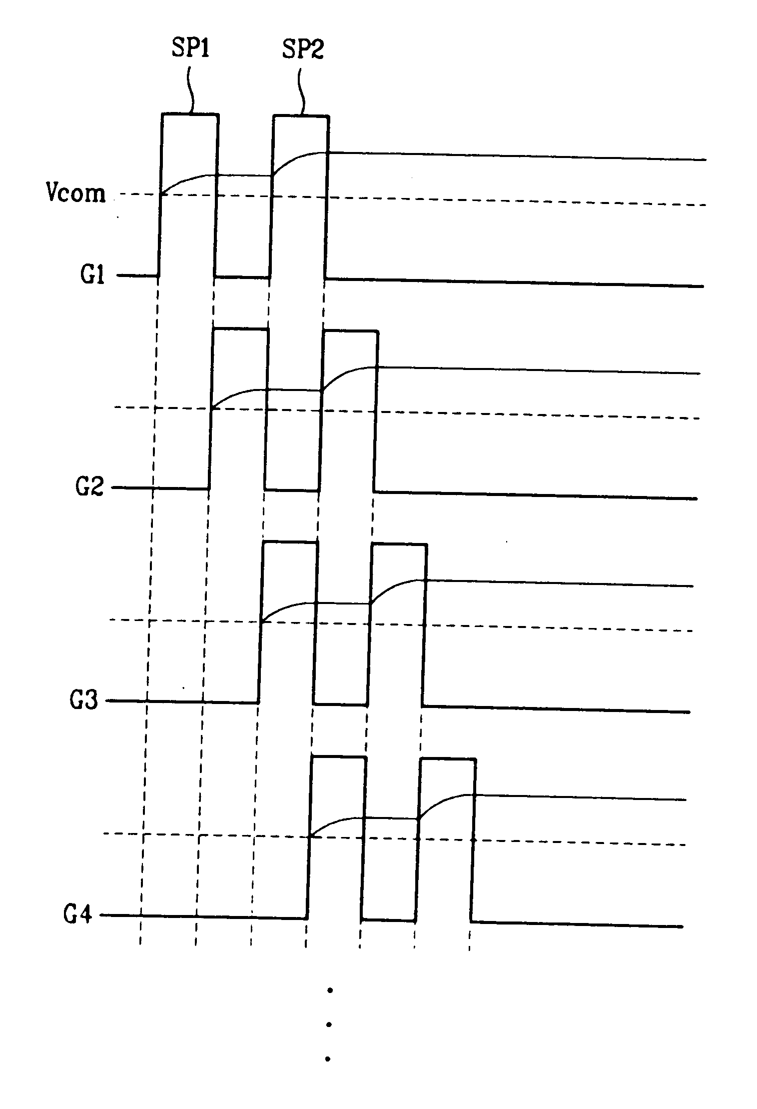
[0030]FIG. 3 is a timing diagram schematically illustrating a method for driving a liquid crystal display (LCD) according to a first exemplary embodiment of the present invention. Referring to FIG. 3, the LCD sequentially applies a scan pulse signal (SP1 and SP2) to first to fourth gate lines (G1 to G4) in order to assign a time interval corresponding to two (2) horizontal periods to a first sub-frame. The scan pulse signal (SP1 and SP2) includes a first scan pulse signal SP1 and a second scan pulse signal SP2. The second scan pulse signal SP2 is spaced apart from the first scan pulse signal SP1 by a time interval of 2 horizontal periods.

[0031]The scan pulse signal (SP1 and SP2) is applied to each of the ga...


PUM


Abstract

A method for driving a liquid crystal display (LCD) in which a single frame is divided into a plurality of sub-frames includes applying a first scan pulse signal and a second scan pulse signal to each gate line for each sub-frame, applying a first data signal to a data line by replying to the first scan pulse signal, applying a second data signal to the data line by replying to the second scan pulse signal, and switching on different light sources at each sub-frame, wherein the first and second scan pulse signals are simultaneously applied to different gate lines. Therefore, the LCD can transmit two scan pulse signals to a single gate line, thereby doubling a driving time of each gate line.

Description

[0001]This application claims the benefit of Korean Patent Application No. 2006-043869, filed in Korea on May 16, 2006, which is hereby incorporated by reference.BACKGROUND OF THE INVENTION[0002]1. Field of the Invention[0003]The present invention relates to a liquid crystal display (LCD), and more particularly, to an LCD that guarantees a sufficient data charging time, and a method for driving the same.[0004]2. Discussion of the Related Art[0005]A variety of flat panel displays having a thickness of only several centimeters (cm) have been marketed throughout the world. A representative example of the flat panel displays is a liquid crystal display (LCD). The LCD usually has a low operation voltage and a low power-consumption, and is suitable for a mobile device. Accordingly, the LCD has been widely used in a variety of application fields such as a notebook computer, a monitor, a spaceship, and an airplane.[0006]The LCD mainly includes a lower substrate, an upper substrate, and a li...

Claims


Application Information

Patent Timeline
IPC IPC(8): G09G3/36
CPCG09G2310/0251G09G2310/0235G09G2310/0205G09G3/3648G02F1/133G09G3/20G09G3/36
Inventor KANG, BYUNG KOOKIM, EUI TAE
Owner LG DISPLAY CO LTD
Why Eureka
Try Eureka