Laser module and method of controlling wavelength of external cavity laser

a laser and laser module technology, applied in the direction of laser details, optical resonator shape and construction, semiconductor lasers, etc., to achieve the effect of accurately adjusting the peak wavelength of the outputting light, and improving the wavelength selection accuracy

Active Publication Date: 2007-11-22
EUDYNA DEVICES INC
View PDF13 Cites 25 Cited by
  • Summary
  • Abstract
  • Description
  • Claims
  • Application Information

AI Technical Summary

Benefits of technology

[0009] In the laser module in accordance with the present invention, a light is amplified by the optical amplifier. The light from the optical amplifier has wavelength peaks at the wavelength interval when passing through the first etalon. A light of a part of wavelength range in the effective gain range is reflected by the wavelength selectable mirror. In this case, peak wavelengths of a light passing through the first etalon are limited by the wavelength selectable mirror. And, it is possible that the wavelength selectable mirror reflects one etalon peak, when the wavelength of the etalon peak is adjusted. The wavelength selection accuracy of outputting light of the laser module is, therefore, improved.
[0026] The external cavity laser may further include a phase sifter controlling a phase of a light passing therethrough when the refractive-index thereof changes. The refractive-index of the external cavity laser may be controlled by the phase shifter. In this case, it is possible to adjust peak wavelengths of the outputting light accurately. It is thus possible to improve the wavelength selection accuracy.

Problems solved by technology

However, the art disclosed in Document 1 has a problem that a full width of half maximum (FWHM) value of the peak of the light passing through the etalon is broadened when a Free Spectral Range (FSR) of the etalon is broadened so that the effective gain range of the semiconductor optical amplifier includes only one of the peak wavelengths of the light passing through the etalon.

Method used


Image

  • Laser module and method of controlling wavelength of external cavity laser
  • Laser module and method of controlling wavelength of external cavity laser
  • Laser module and method of controlling wavelength of external cavity laser

Examples


first embodiment

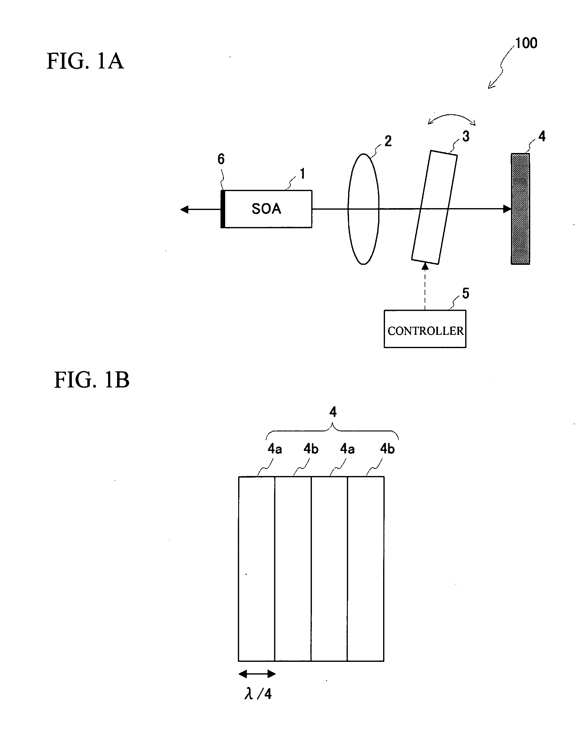
[0039]FIG. 1A and FIG. 1B illustrate a schematic view of an optical communication device in accordance with a first embodiment. FIG. 1A illustrates an overall view of the optical communication device. FIG. 1B illustrates a cross sectional view of a wavelength selectable mirror 4. As shown in FIG. 1A, a laser module 100 has a semiconductor optical amplifier 1, a lens 2, an etalon 3 and the wavelength selectable mirror 4. The optical communication device in accordance with the embodiment has the laser module 100 and a controller 5 controlling the laser module 100. The lens 2, the etalon 3 and the wavelength selectable mirror 4 are arranged backward of the semiconductor optical amplifier 1 in order.

[0040] The semiconductor optical amplifier 1 amplifies an incident light having a given effective wavelength range, and contributes a laser oscillation. A mirror 6 is arranged in front of the semiconductor optical amplifier 1. The laser light from the semiconductor optical amplifier 1 is re...

second embodiment

[0053]FIG. 3 illustrates a schematic view of a laser module 100a in accordance with a second embodiment. The laser module 100a is different from the laser module 100 in FIG. 1A in a point that a fixed etalon 7 is provided instead of the etalon 3. Here, the fixed etalon is an etalon having a fixed refractive-index. The fixed etalon 7 is fixed in the laser module 10a. A cavity length of the fixed etalon 7 is determined so that the etalon peaks of the fixed etalon 7 are within the reflection bandwidth R of the wavelength selectable mirror 4. The inclination of the fixed etalon 7 is determined so that the reflection bandwidth R of the wavelength selectable mirror 4 has one of the etalon peaks of the fixed etalon 7.

[0054]FIG. 4A thorough FIG. 4D illustrate a laser light resonating in the laser module 100a. FIG. 4A illustrates a wavelength range of a laser light emitted from the semiconductor optical amplifier 1. FIG. 4B illustrates transmission characteristics of the fixed etalon 7. FIG...

third embodiment

[0060]FIG. 5 illustrates a schematic view of an optical communication device in accordance with a third embodiment. A laser module 100b employed for the optical communication device is different from the laser module 100 in FIG. 1 in a point that liquid crystal etalons 8 and 9 are provided instead of the etalon 3. The lens 2, the liquid crystal etalon 8, the liquid crystal etalon 9, and the wavelength selectable mirror 4 are arranged backward of the semiconductor optical amplifier 1 in order, in the laser module 100b.

[0061] The liquid crystal etalons 8 and 9 are composed of a liquid crystal band-pass filter transmitting a light at a given wavelength interval. The refractive-indexes of the liquid crystal etalon 8 and 9 change according to a voltage applied thereto by the controller 5. The etalon peak wavelengths of the liquid crystal etalons 8 and 9 change according to the refractive-index thereof.

[0062]FIG. 6A through FIG. 6F illustrate a laser light resonating in the laser module...


PUM


Abstract

A laser module has an optical amplifier, a first etalon and a wavelength selectable mirror. The first etalon has wavelength peaks at a given wavelength interval in transmission characteristics and transmits a light from the optical amplifier. The wavelength peaks are tunable. The wavelength selectable mirror acts as an external mirror of an external cavity laser including the optical amplifier, and has a relatively high reflection intensity at a part of wavelength range in an effective gain range of the optical amplifier. The effective gain range of the optical amplifier includes more than one wavelength peak of the first etalon. A reflection bandwidth where the wavelength selectable mirror has a relatively high reflection intensity is less than twice of the wavelength interval of the wavelength peaks of the first etalon.

Description

BACKGROUND OF THE INVENTION [0001] 1. Field of the Invention [0002] This invention generally relates to a laser module and a method of controlling wavelength of an external cavity laser. [0003] 2. Description of the Related Art [0004] Recently, an information-processing device and so on using a semiconductor laser have been developed. There is a demand for superior characteristics such as tunability or stability of wavelength. And so, Japanese Patent Application Publication No. 2003-152275 (hereinafter referred to as Document 1) discloses an art in which a wavelength selectable etalon whose inclination is tunable is provided between a semiconductor optical amplifier and an external mirror. [0005] In accordance with the art, peak wavelengths of a light passing through an etalon change when the inclination of the etalon is changed. And, an effective gain range of the semiconductor optical amplifier includes one of the peak wavelengths. Therefore, an output wavelength of the semiconduc...

Claims


Application Information

Patent Timeline
Patent Type & Authority Applications(United States)
IPC IPC(8): H01S3/08H01S3/00
CPCH01S3/1062H01S5/0612H01S5/141H01S5/0683H01S5/0687H01S5/0617
Inventor HIGASHI, TOSHIOYAMAUCHI, YASUYUKIDE GABORY, EMMANUEL LE TAILLANDIERTANAKA, HIROKAZUWATANABE
Owner EUDYNA DEVICES INC
Why Eureka
Try Eureka