Method and apparatus for controlling a haptic device

a haptic device and control method technology, applied in the field of surgical systems, can solve the problems of increasing the complexity of sculpting bone and assessing the proper implant position, reducing the surgeon's ability, and reducing the accuracy of implant placement,

a haptic device and control method technology, applied in the field of surgical systems, can solve the problems of increasing the complexity of sculpting bone and assessing the proper implant position, reducing the surgeon's ability, and reducing the accuracy of implant placement,

US20070270685A1Active Publication Date: 2007-11-22MAKO SURGICAL CORP

Image

  • Method and apparatus for controlling a haptic device
  • Method and apparatus for controlling a haptic device
  • Method and apparatus for controlling a haptic device

Examples


Embodiment Construction

[0033]Presently preferred embodiments of the invention are illustrated in the drawings. An effort has been made to use the same or like reference numbers to refer to the same or like parts.

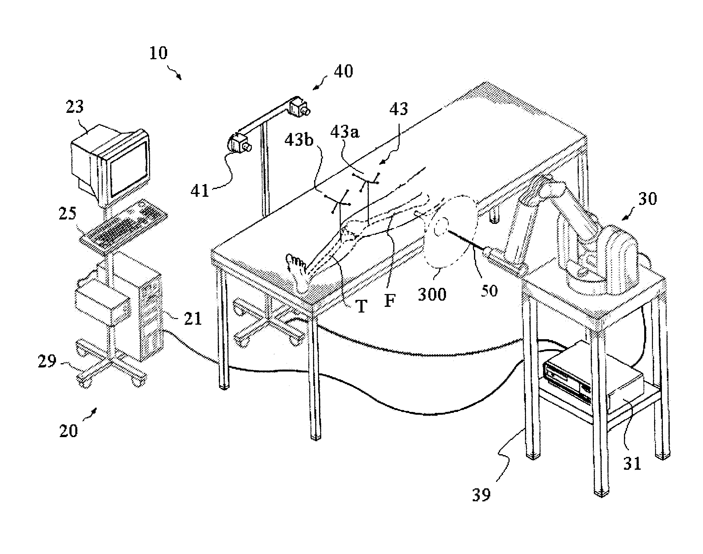
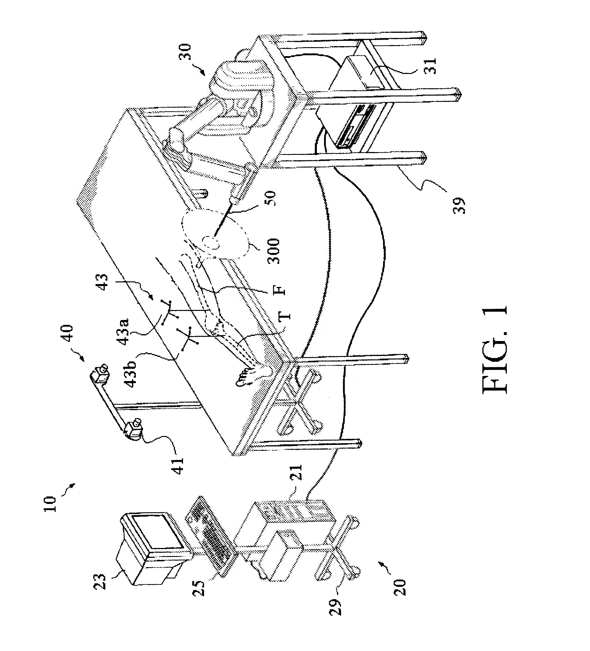
[0034]FIG. 1 shows an embodiment of a surgical system 10. The surgical system 10 includes a computing system 20, a haptic device 30, and a tracking system 40. In one embodiment, the surgical system 10 is a robotic surgical system as disclosed in U.S. patent application Ser. No. 11 / 357,197, Pub. No. US 2006 / 0142657, filed Feb. 21, 2006, and incorporated by reference herein in its entirety. In a preferred embodiment, the surgical system 10 is the HAPTIC GUIDANCE SYSTEM™ available from MAKO SURGICAL CORP.® in Ft. Lauderdale, Fla.

[0035]The computing system 20 includes hardware and software for operation and control of the surgical system 10 and may comprise a computer 21, a computer 31, a display device 23, an input device 25, and a cart 29. The computing system 20 is adapted to enable the surgical sy...


PUM


Abstract

A method for calibrating a surgical device is provided. The method includes acquiring first data including a position and / or an orientation of a first object disposed on the surgical device at a first location; acquiring second data including a position and / or an orientation of a second object disposed on the surgical device at a second location; determining third data including a position and / or an orientation of the first object relative to the second location; and determining a position and / or an orientation of the second object relative to the second location based at least in part on the first data, the second data, and the third data.

Description

CROSS REFERENCE TO RELATED APPLICATIONS[0001]This application claims priority from U.S. Provisional Patent Application Ser. No. 60 / 801,378, filed May 19, 2006, the disclosure of which is hereby incorporated by reference herein in its entirety.BACKGROUND OF THE INVENTION[0002]1. Field of the Invention[0003]The invention relates to a surgical system and, more particularly, to method and apparatus for controlling a haptic device.[0004]2. Description of Related Art[0005]Minimally invasive surgery (MIS) is the performance of surgery through incisions that are considerably smaller than incisions used in traditional surgical approaches. For example, in an orthopedic application such as total knee replacement surgery, an MIS incision length may be in a range of about 4 to 6 inches whereas an incision length in traditional total knee surgery is typically in a range of about 6 to 12 inches. As a result of the smaller incision length, MIS procedures are generally less invasive than traditional...

Claims


Application Information

Patent Timeline
22 Nov 2007
Publication
US20070270685A1
IPC
A61B5/05
CPC
A61B17/1764; A61B2019/5483; A61B19/30; A61B19/5244; A61B19/56; A61B2017/00119; A61B2017/00694; A61B2017/00712
Inventors
KANG, HYOSIG; MOSES, DENNIS