Locking device and method, for use in a bone stabilization system, employing a set screw member and deformable saddle member

a locking device and bone stabilization technology, applied in the field of orthopaedic implants, can solve the problems of increasing reducing the stress level realized within the secured stabilization member, and many locking mechanisms utilized in the bone stabilization system potentially causing component failure, so as to reduce the creation of surface stress risers, increase the potential for post-operative failure, and reduce the stress realized in the stabilization member

Inactive Publication Date: 2007-11-22
WARSAW ORTHOPEDIC INC
View PDF36 Cites 117 Cited by
  • Summary
  • Abstract
  • Description
  • Claims
  • Application Information

AI Technical Summary

Benefits of technology

[0010] Connecting the stabilization member, the bone fastener and the coupling device together in a bone stabilization system can result in high forces being exerted onto the stabilization member, thereby increasing the potential for post-operative failure to occur. Thus, a need exists for the use of a deformable material for securing the stabilization m

Problems solved by technology

Connecting the stabilization member, the bone fastener and the coupling device together in a bone stabilization system can result in high forces being exerted onto the stabilization member, thereby increasing the potential for post-operative failure to occur.
Currently, many locking mechanisms utilized in bone stabilization systems potentially induce component failure during in vivo post-o

Method used


Image

  • Locking device and method, for use in a bone stabilization system, employing a set screw member and deformable saddle member
  • Locking device and method, for use in a bone stabilization system, employing a set screw member and deformable saddle member
  • Locking device and method, for use in a bone stabilization system, employing a set screw member and deformable saddle member

Examples


Embodiment Construction

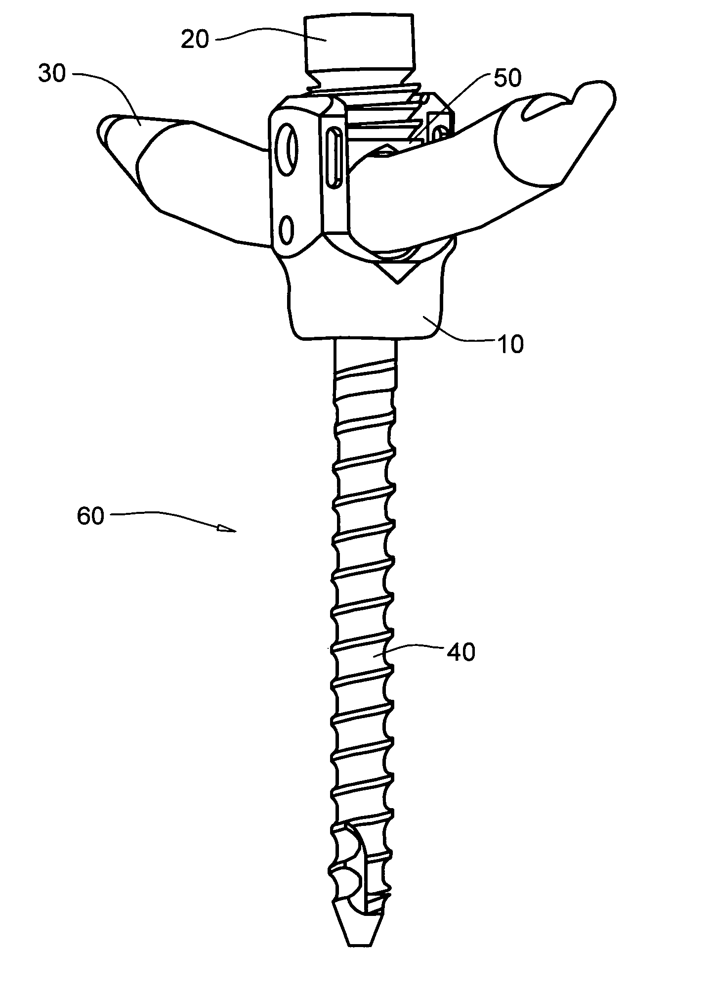
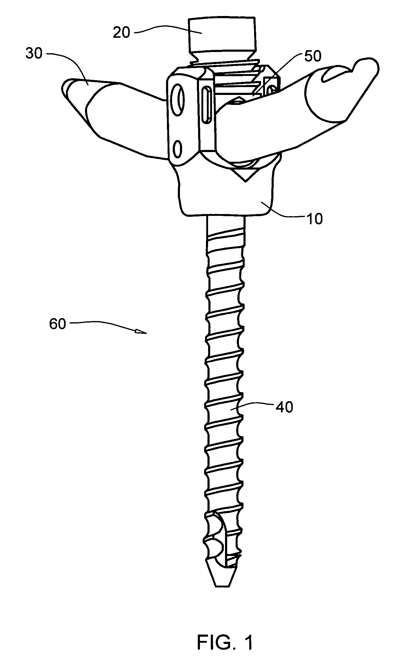
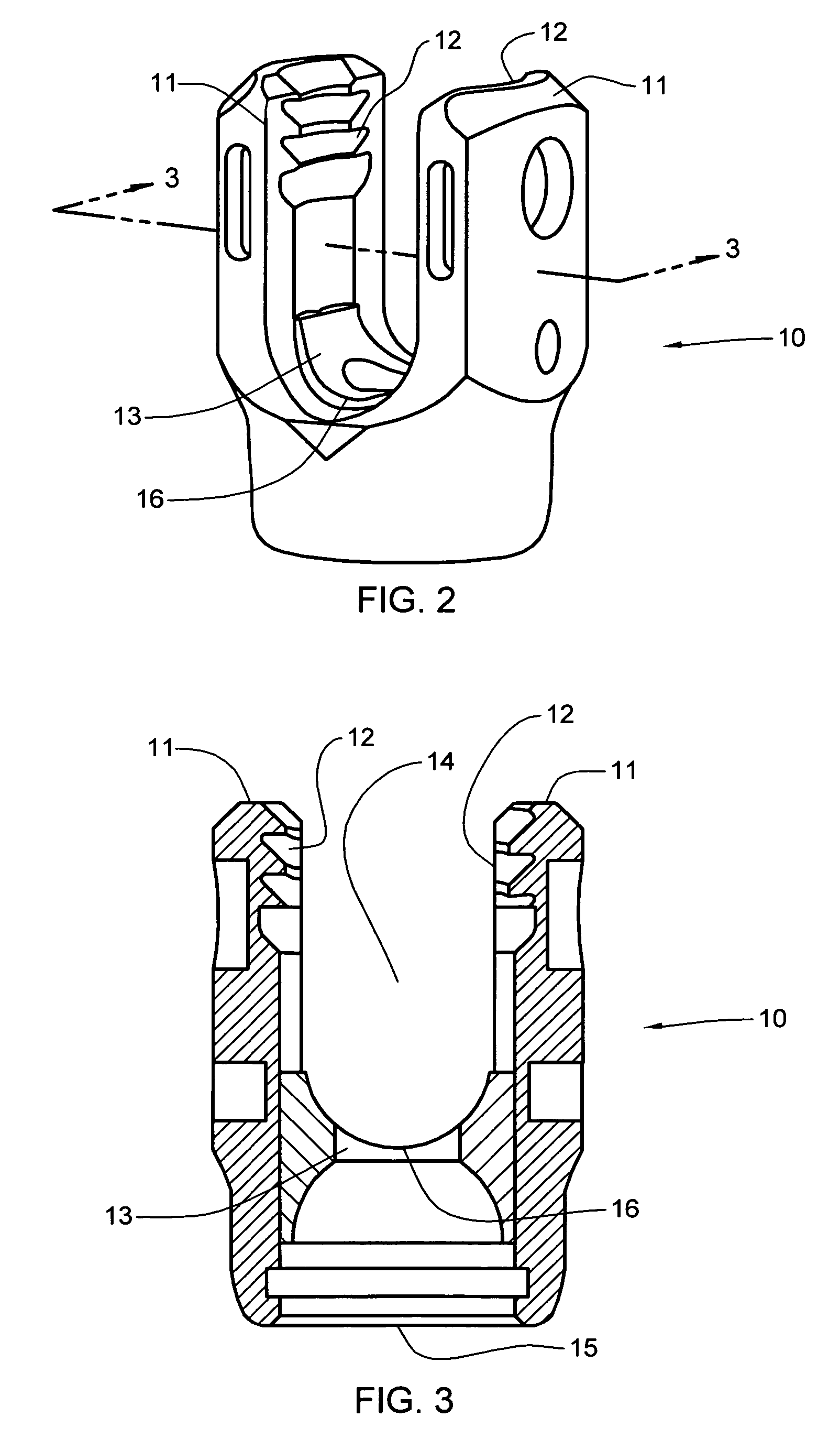
[0030] As depicted in FIG. 1, the general arrangement of a bone stabilization system 60, in accordance with an aspect of the present invention, includes a coupling mechanism 10, a locking device, comprising a set screw member 20 and a saddle member 50, a stabilization member 30, and a bone anchor 40. When used in the spine to secure multiple levels of the spinal column, a bone anchor 40 is placed within an individual vertebrae and a coupling mechanism 10 is then attached to each implanted bone fastener 40. Following placement of multiple bone anchors and coupling mechanisms, an appropriately dimensioned stabilization member 30, which spans the levels of the affected vertebral region, is placed within the coupling mechanisms 10 and secured in place employing multiple locking devices. As noted, the locking device includes set screw member 20 and saddle member 50. When the locking device is in use stabilization member 30 is frictionally held in place between coupling mechanism 10 and t...


PUM


Abstract

A set screw with a deformable saddle for use in securing a stabilization member within a bone stabilization system. The bone stabilization system includes a bone anchor, a stabilization member, a coupling mechanism and a locking device. The locking device is structured to engage the coupling mechanism and the coupling mechanism is configured to couple the stabilization member to the bone anchor. The locking device which is configured to thread into the coupling mechanism, includes a set screw connected to a saddle member. The saddle member is fabricated from a deformable material. The locking device is configured to frictionally secure the stabilization member within the coupling mechanism by the application of a compressive force.

Description

CROSS-REFERENCE TO RELATED APPLICATIONS / PATENTS [0001] This application contains subject matter which is related to the subject matter of the following applications / patents, which are hereby incorporated herein by reference in their entirety: [0002]“Multi-Axial Bone Attachment Assembly”, Coates et al., U.S. Ser. No. 10 / 870,011, filed Jun. 17, 2004, and published on Dec. 22, 2005 as Patent Application Publication No. US 2005 / 0283157 A1; [0003]“Coupling Assemblies for Spinal Implants.”, Justis et al., U.S. Ser. No. 11 / 197,799, filed Jan. 31, 2006; [0004]“Force Limiting Coupling Assemblies for Spinal Implants”, Justis et al., U.S. Ser. No. 11 / 112,221, filed Jan. 31, 2006; and [0005]“Bone Anchor System Utilizing A Molded Coupling Member For Coupling A Bone Anchor To A Stabilization Member And Method Therefor”, Dewey, et al, U.S. Ser. No. ______, co-filed herewith (Attorney Docket No.: P23147.00).TECHNICAL FIELD [0006] The present invention relates generally to orthopaedic implants used ...

Claims


Application Information

Patent Timeline
IPC IPC(8): A61F2/30
CPCA61B17/7004A61B17/7011A61B2019/307A61B17/7037A61B17/7032A61B2090/037A61B17/68A61B17/70A61B17/84A61B17/86
Inventor MOORE, JEFFREY D.
Owner WARSAW ORTHOPEDIC INC
Why Eureka
Try Eureka