
Thin Film Metallic Devices for Plugging Aneurysms or Vessels

a technology of metallic devices and aneurysms, applied in the field of medical devices, can solve the problems of forming an occlusion thrombosis and stagnating blood within the aneurysm

Inactive Publication Date: 2007-11-22
DEPUY SYNTHES PROD INC
View PDF12 Cites 206 Cited by
  • Summary
  • Abstract
  • Description
  • Claims
  • Application Information

AI Technical Summary

Benefits of technology

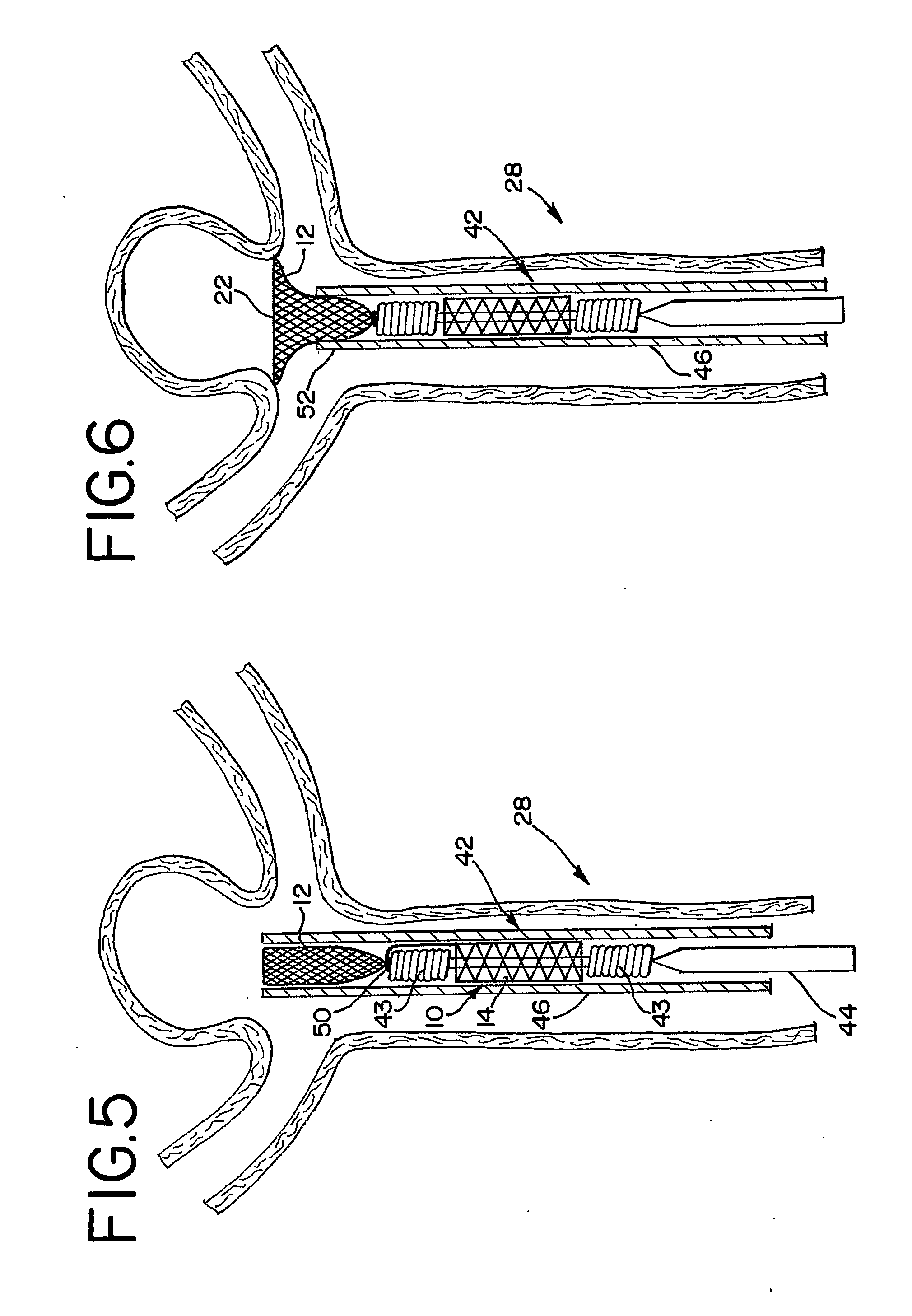
[0023] In accordance with the present invention, occlusion devices and methods are provided for treating a diseased vessel of a patient, and more particularly for treating an aneurysm. The invention is especially suitable for treating a distal basilar tip aneurysm. The occlusion device includes an embolization element which is connected to an anchor element that aids in maintaining the embolization element in place.
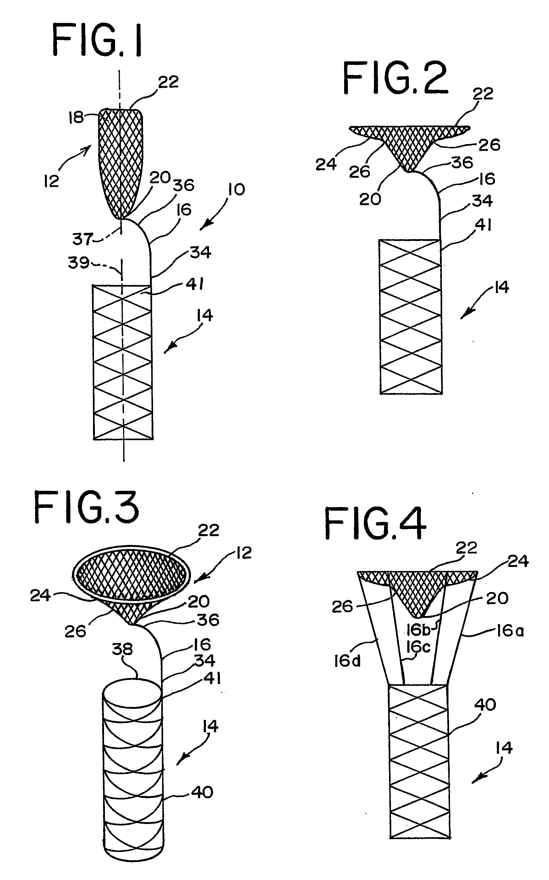
[0024] The embolization element has a thin film structure that has a contracted or collapsed configuration which facilitates endoluminal deployment as well as an expanded or deployed configuration for plugging an aneurysm. When in the deployed configuration, the thin film of the embolization element is shaped with a distal end of a larger cross-sectional extent when compared to the rest of the deployed device. Such deployed shapes can be generally funneled in shape or hemispherically shaped.
[0025] When the occlusion device is deployed, the embolization element plugs an aneurysm by abutting the larger distal end of the embolization element against a wall of an artery surrounding the outside of a neck of the aneurysm, or by placing the embolization element within the aneurysm so that the proximal end of the embolization element plugs the neck of the aneurysm. The porosity of the embolization element is low enough to either substantially reduce or fully block the flow of blood into or out of the aneurysm. This causes the blood to stagnate within the aneurysm and form an occluding thrombus. Additionally, it is preferred that the shape of the embolization element also substantially reduces turbulence and aids in maintaining a substantially laminar blood flow in the vicinity of the implanted device.
[0027] An anchor element that is connected to the embolization element by a connector element aids in retaining the embolization element in place and reduces the risk of the embolization element becoming dislodged and migrating to an undesired location. The anchor element is preferably a self expanding stent, but may also be a balloon expandable stent or any other suitable anchor member.

Problems solved by technology

This causes the blood to stagnate within the aneurysm and form an occluding thrombus.

Method used


Image

  • Thin Film Metallic Devices for Plugging Aneurysms or Vessels
  • Thin Film Metallic Devices for Plugging Aneurysms or Vessels
  • Thin Film Metallic Devices for Plugging Aneurysms or Vessels

Examples


Embodiment Construction

[0042] As required, detailed embodiments of the present invention are disclosed herein; however, it is to be understood that the disclosed embodiments are merely exemplary of the invention, which may be embodied in various forms. Therefore, specific details disclosed herein are not to be interpreted as limiting, but merely as a basis for the claims and as a representative basis for teaching one skilled in the art to variously employ the present invention in virtually any appropriate manner.

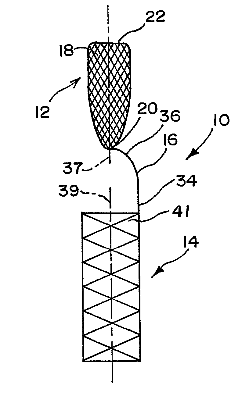
[0043]FIG. 1 generally illustrates a preferred embodiment of an occlusion device of the present invention in the contracted or collapsed position. The occlusion device 10 comprises an embolization element 12 attached to an anchor element 14 by a connector element 16.

[0044] The embolization element 12 preferably comprises a thin film formed by physical vapor deposition onto a core or mandrel, as is well-known to those skilled in the art. Most preferably, a thin film of a nitinol (which encompasse...


PUM


Abstract

Thin film metallic devices implantable within a human subject for occlusion of an aneurysm or blood vessel are provided. The devices include an embolization element that is moveable between a collapsed configuration for delivery to a deployed configuration within the body. The embolization device plugs the aneurysm or blood vessel preventing blood from flowing into or out of the aneurysm or other defective or diseased location of the blood vessel. The embolization element may be either self-supporting or supported by a strut structure. The occlusion device also includes an anchor element for anchoring the occlusion device and aiding in maintaining the embolization element in place. The anchor element is connected to the embolization device via a connector element.

Description

CROSS REFERENCE TO RELATED APPLICATION [0001] This application claims priority from provisional patent application Ser. No. 60 / 611,016, filed Sep. 17, 2004, which is hereby incorporated herein by reference.FIELD OF THE INVENTION [0002] This invention generally relates to medical devices that are implantable within a vessel of a patient and that have occlusion capabilities that are especially suitable for use as medical device plugs for aneurysms or for defective or diseased body vessels. These types of devices have a shape which diverts blood flow away from aneurysms and a porosity that reduces or prevents blood from flowing into or out of an aneurysm. DESCRIPTION OF RELATED ART [0003] Medical devices that can benefit from the present invention include those that are introduced endoluminally and expand when deployed so as to plug up a location of concern within the patient. These are devices that move between collapsed and expanded conditions or configurations for ease of deployment...

Claims


Application Information

Patent Timeline
IPC IPC(8): A61M29/00
CPCA61B17/12022A61B17/12118A61B17/12172A61F2/86A61F2002/823A61F2230/008A61F2220/005A61F2220/0058A61F2230/0067A61F2230/0078A61F2210/0076
Inventor SLAZAS, ROBERT R.JONES, DONALD K.
Owner DEPUY SYNTHES PROD INC
Learn More